EMX Industries, Inc. Tech support: 216-518-9889 4/6
IRB-MON_Rev3.3_072720 technical@emxinc.com
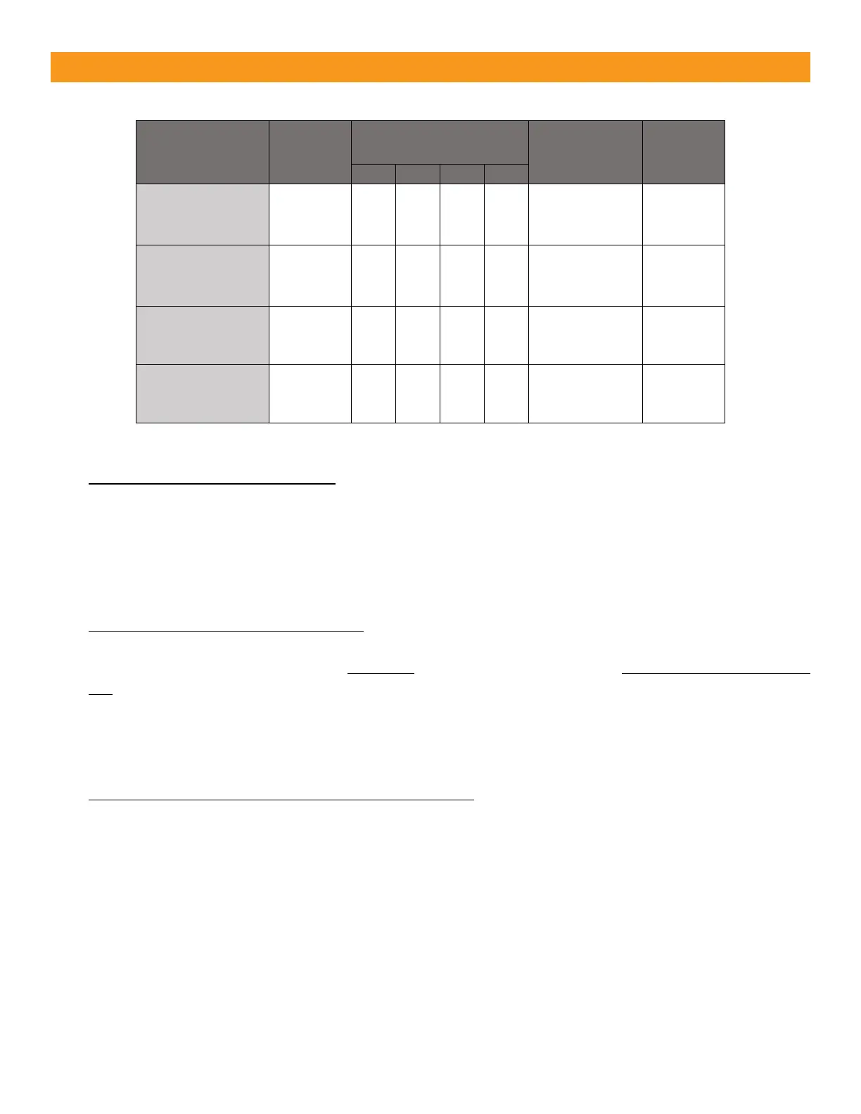
• FAIL SAFE (Wiring Diagram A or B) – Most common monitoring method - Gate opens with loss of
power - DIP switches shown as in the table above for monitored “Normally Closed” and “10K Resistive
Termination”. The relay will change state during a loss of power (N.C. will open, and N.O. will close).
It is also sometimes referred to as Dark ON as the N.C. relay contact will be in the closed position and
N.O. contact in the open position when under power and NOT obstructed (aligned).
WARNING: Use this mode in all normal operations and UL325 monitoring scenarios.
• FAIL SECURE (Wiring Diagram A or B) – Less common monitoring method, Gate closes/secures
with loss of power - To achieve Fail Secure for either “Normally Closed” or “10K resistive
termination”, configure dipswitches the same as shown in the above table “EXCEPT” SW1 needs to be
ON. Fail Secure is sometimes referred to as Light ON. The relay will function in reverse (opposite what
is written on the PCB). When powered on and aligned the N.O. relay will be closed, and the N.C.
contact will be open. The relay WILL NOT change states during loss of power so the gate stays closed
during power loss (N.O. will close, and N.C. will open).
• Two-Wire Pulse Monitoring (Wiring Diagram C or D) – Must use 6-35 VDC (can’t use AC power in
two-wire pulse mode) and requires a compatible operator board with the current limiting resistor.
Note: If using the IRB-MON in an application that does not require UL325 monitoring across the
normally open contact, it is possible to disable the 10K resistor by using Wiring Diagram A DIP switch
setting, but connect to N.O. relay.
 Loading...