EMX Industries, Inc. Tech support: 216-518-9889 3/6
IRB-MON_Rev3.3_072720 technical@emxinc.com
• Determine the mounting location of the IRB-MON photoeye according to UL325 guidelines.
• Deactivate the gate or door during photoeye installation.
• The IRB-MON cannot be used for a detection range of less than 5 feet.
1. Check the instruction manual of the gate or door operator
to determine which monitoring method is necessary for
that specific operator.
2. Knock out the PG hole on the housing that will be used to
wire through. Be careful not to damage electronic circuit
board when knocking out the hole.
3. Connect 6-35 VDC or 12-24 VAC power to the “Power Input”
terminals on the transmitter (marked “TX”) and receiver
(marked “RX”.) The power input terminals are not polarity
sensitive.
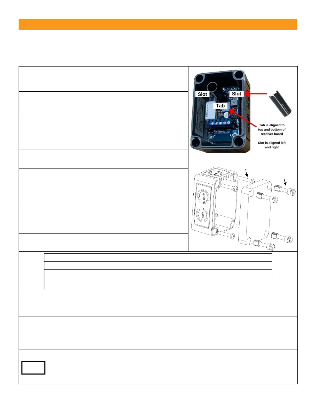
4. Install optional sunshield on receiver as shown to the right
to reduce the effects of solar interference or cross talk.
5. Wire the IRB-MON according to the configuration table and
wiring diagram that corresponds with the monitoring
method required by the gate or door operator.
MUST USE 6-35 VDC FOR PULSE MONITORING.
6. Make sure the covers are attached and closed tight using
all four plastic screws provided as shown. The wiring to the
enclosure must enter via UL listed watertight fitting such as
a strain relief or watertight conduit connector.
7. Verify that the IRB-MON transmitter and receiver are
aligned and apply power.
Green receiver LED flashing
Beam blocked or not aligned
8. The receiver and transmitter are aligned correctly when the green LED on the receiver is on. Decrease
the sensitivity setting on the receiver to the position where the green LED on the receiver starts to flash.
Then increase sensitivity setting one quarter turn. Confirm receiver LED is still on.
9. Place an obstruction (ex. hand) between the IRB-MON transmitter and receiver. The green LED on the
receiver will flash. Check the operator control board and verify that the safety input is recognized by
the operator. Test the beam with an obstruction between transmitter and receiver at multiple distances
to confirm proper operation.
10. Remove the obstruction and the green LED will turn on.
If the IRB-MON is aligned but not detecting an obstruction, consider slowly reducing sensitivity
(counter-clockwise) on the receiver until the obstruction is detected. This may be applicable for
installations with a detection zone of less than 20 ft.
 Loading...