TERMS
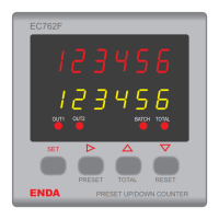
(3) State indicators shows the state of the counter.
(7) Used for selecting run or programming modes or for adjusting parameters.
(4) To see the total result press this key in the run mode.
Increment or parameter selection key during programming mode.
(5) Reset key in the run mode.
Decrement or parameter selection key during programming mode
(6) Used for selecting preset value in the run mode.
Used for selecting oPtion. s or parameter to be changed in the programming mode.
(2)
The value of the parameter selected by parameter during run mode.
Parameter value during programming mode.
(1) The value of the parameter selected by parameter during run mode.
Parameter name during programming mode.
ENDA
PRESET UP/DOWN COUNTER
OUT1
OUT2
BATCH
TOTAL
PRESET
TOTAL
RESET
SET
EC762F
Panel cut-out
Connection
cables
Depth
97mm
75mm
84mm
DIMENSIONS
68 mm
+0.7
68 mm
+0.7
Rubber packing
Flush mounting
clamp
Panel
72mm
78mm
1
2
PRESET UP/DOWN COUNTER
RESET
TOTAL
BATCH
TOTAL
PRESET
OUT2
OUT1
EC762F
ENDA
SET
2/5
EC762F-E-04
CONNECTION DIAGRAM
11
12
13
14
15
16
17
18
INDUSTRIAL
ELECTRONICS
SN: XXXXXXXXX
EC762F-24AC
ENDA
OUT1
AC 250V 2A
RESISTIVE
LOAD
OUT2
AC 250V 2A
RESISTIVE
LOAD
24V AC ±10%
50/60Hz 7VA
4 RESET IN
5 S.S. OUT2
6 S.S. OUT1
7 CP2 INPUT
8 CP1 INPUT
10 +12V 50mA
9 GND
11
12
13
14
15
16
17
18
INDUSTRIAL
ELECTRONICS
SN: XXXXXXXXX
ENDA
EC762F
OUT1
AC 250V 2A
RESISTIVE
LOAD
OUT2
AC 250V 2A
RESISTIVE
LOAD
230V AC +10% -20%
50/60Hz 7VA
10 +12V 50mA
4 RESET IN
5 S.S. OUT2
6 S.S. OUT1
7 CP2 INPUT
8 CP1 INPUT
9 GND
12
11
184-253V AC
50/60Hz 7VA
Switch
Fuse
F 100 mA
250V AC
Neutral
Line
SUPPLY :
NOTE :
disp.
config
disp.
config
Digital display (1) : 9.1mm
Digital display (2) : 7.1mm
4 red LEDs
6 digits, seven segment red LED
6 digits, seven segment yellow LED
Micro switch
( 2 ) Digital display
Character height
( 3 ) State indicators
( 4 ),( 5 ),( 6 ),( 7 ) Keypad
( 1 ) Digital display
Note 1) While panel mounting, additional distance required for
connection cables should be considered.
2) Panel thickness should be maximum 10mm.
3) If there is no 90mm free space at back side of the device,
it would be difficult to remove it from the panel.
- Push up the flush-mounting
clamp in direction 1 as
shown in the figure above.
- Then, pull out the clamp in
direction 2.
For removing mounting clamps:
ENDA EC762F is intended for installation in control panels. Make sure that the device is used only for intended
purpose. During an installation, all of the cables that are
connected to the device must be free of energy. The device must be protected against inadmissible humidity,
vibrations, severe soiling and make sure that the operation temperature is not exceeded. All input and output
lines that are not connected to the supply network must be laid out as shielded and twisted cables. These cables
should not be close to the power cables or components.
The shielding must be grounded on the instrument side.
The installation and electrical connections must be
carried on by a qualified staff and must be according to the relevant locally applicable regulations.
Fuse should
be connected.
230V AC Supply
Cable size: 1,5mm²
1) Mains supply cords shall meet the requirements of IEC 60227
or IEC 60245.
2) In accordance with the safety regulations, the power supply
switch shall bring the identification of the relevant instrument
and it should be easily accessible by the operator.
Note :
Holding screw 0.4-0.5Nm
Equipment is protected throughout
by DOUBLE INSULATION.
 Loading...