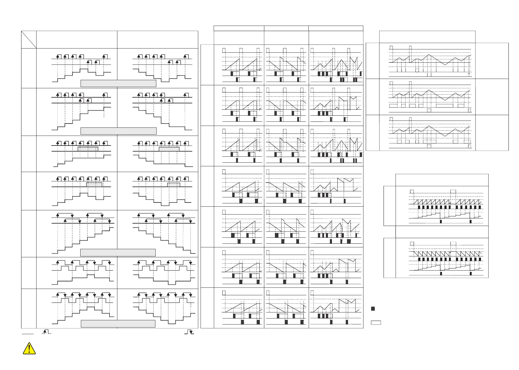
OUTPUT TYPES
Config
2
Config
1
Reset
999,999
Preset2
Preset1
0
Out1
Out2
999,999
Preset2
Reset
Preset1
0
Out1
Out2
Config
3
Reset
Preset1
0
Out1
Out2
999,999
Preset2
Config
4
Reset
Preset1
0
Out1
Out2
999,999
Preset2
Config
5
Reset
Preset1
0
Out1
Out2
999,999
Preset2
Config
6
Reset
Preset1
0
Out1
Out2
999,999
Preset2
Config
7
Reset
Preset1
0
Out1
Out2
999,999
Preset2
= , ,
= , ,
=
=
dirEct
oppos.
= , , ,= , , ,
Countr.
dir.
Countr.
dir.
Countr.
dir.
= dýrEct.
Countr.
dir.
= oPPos.
Config
bAtch
Out1
Out2
Preset1
Preset2
Reset
999,999
0
Batch
Counter 0
Config
bAtch
Out1
0
Out2
Preset1
Preset2
Reset
999,999
-99,999
Config
10
Config
8
Reset
999,999
Preset2
Preset1
0
Out1
Out2
-99,999
Config
9
Reset
999,999
Preset2
Preset1
0
Out1
Out2
-99,999
oPPoS.
n+1
n+2
n+2
n+2
n+2
n+3
n+3
n+4 n+4
n+5
n+4
n+3 n+3
n+5
n+5
n+4
n+6
n+6
n+7
n+7
n+8
n+3
n+3
n+4
n+4
Count
input CP1
Count
input CP1
Count
input CP1
Count
input CP1
Count
input CP1
Count
input CP1
H
H
H
H
H
H
H
H
H
H
H
H
L
L
L
L
L
L
L
L
L
L
L
L
n
n
n-1
n-1
n-1
n-2
n-2
n-2
n-2
n-3
n-3
n-3
n-4
n-4
n-5
Count
input CP2
Count
input CP2
Count
input CP2
Gate
input CP2
Count
input CP2
Count
input CP2
DISPLAY
DISPLAY
DISPLAY
DISPLAY
DISPLAY
DISPLAY
Count
input CP1
H
H
L
L
dirction
input CP2
DISPLAY
n
n
n
n
n
n-1
n-1
n-1
n-1
n-1
n-2
n-2
n-2
n-2
n-2
n-2
n-2
n-3
n-3
n-3
n-4
n-3
n-3
n-3
n-4
n-5
n-5
n-6
n-6
n-7
n-7
n-8
n-3
n-4
n-3
n-4
INPUT TYPES
Out1
Out2
Preset1
Preset2
Reset
999,999
0
Batch
Counter 0
While Batch counter mode is selected, decimal point is not seen.
Because, Prset2 and batch counting values are integer.
inPut
tyPE
Countr.
dir.
dirEct.
CP1-UP
CP2-dn
CP1-UP
CP2-UP
UP
Ph-4
UP-dn
Ph-1
UP-dn
Ph-2
CP1-UP
CP2-Gt
CP1-UP
CP2.dýr
Count
input CP1
Count
input CP1
Count
input CP1
Count
input CP1
Count
input CP1
Count
input CP1
H
H
H
H
H
H
H
H
H
H
H
H
L
L
L
L
L
L
L
L
L
L
L
L
n
n
n
n
n
n
n
n+1
n+1
n+1
n+1
n+1
n+1
n+1
n+2
n+2
n+2
n+2
n+2
n+2
n+2
n+3
n+3
n+3
n+3
n+3
n+3
Count
input CP2
Count
input CP2
Count
input CP2
Count
input CP2
Count
input CP2
Gate
input CP2
DISPLAY
DISPLAY
DISPLAY
DISPLAY
DISPLAY
DISPLAY
Count
input CP1
H
H
L
L
direction
input CP2
DISPLAY
Note: The maximum value of the input frequency can be
one half of the selected value (inPut. Frq.)
Note: The maximum value of the input frequency can be
one half of the selected value (inPut. Frq.)
Note: The maximum value of the input frequency can be
1/3 of the selected value (inPut. Frq.)
Note: The maximum value of the input frequency can be
2/3 of the selected value (inPut. Frq.)
4/5
EC762F-E-04
inPut
typE
inPut
typE
inPut
typE
inPut
typE
CP1-UP
CP2-dn
CP1-UP
CP2-dn
CP1-UP
CP2-UP
CP1-UP
CP2-UP
CP1-UP
CP2-Gt.
CP1-UP
CP2-Gt.
CP1-UP
CP2.dir.
CP1-UP
CP2.dir.
UP
Ph-4
UP
Ph-4
UP-dn
Ph-1
UP-dn
Ph-1
UP-dn
Ph-2
UP-dn
Ph-2
OUTPUT TYPES
out2
ti.
out2
ti.
Adjusting or to a value between 0.01 and 999.9 seconds,
a pulse output is obtained.
Adjusting or to 0.0, a continuous output is obtained.
out1
ti.
out1
ti.
While counter is
equal to Preset1
and Preset2 values,
OUT1 and OUT2
becomes active
respectively.
While counting value
is lower or equal to
the Preset1 and
Preset2 values,
OUT1 and OUT2
becomes active
respectively.
While counting value
is greater or equal to
the Preset1 and
Preset2 values,
OUT1 and OUT2
becomes active
respectively.
UP COUNTER
DOWN COUNTER UP / DOWN COUNTER
(HOLD)
(Autoreset)
(Delayed
Autoreset)
(Delayed
Autoreset
and HOLD)
(Autoreset and
Display hold)
For PNP sensor, counter is triggered at the rising edge of the pulses.
For NPN sensor, if you select ýnPt.tyPE CP1.U. CP2.r. , above diagram for Cntr.dýr. DýrE replaces with Cntr.dýr OPPo. .
NOTE :
For NPN sensor counter is triggered at the falling edge of the pulses.
1)
2)
Input frequency should not exceed the values indicated above. Otherwise, counter value will be wrong.
 Loading...