C.E.c,t. = Faulty sensor control type.
If C.E.c.t. = E..P.S. , in the case of probe
failure according to C.E.P.S. proportional
value of the parameter control is performed.
If C.E.c.t = Auto. in the case of probe
failure, the fault found and recorded before
the last setpoint control with the control
percentage is performed.
SET
C/A SET
C/A SET
SET
F
F
F
A2SET
SET
C/A SET
F
Entering from the "Programming Mode" to the "Running mode":
If no key is pressed within 20 seconds during "Programming Mode", the data is stored automatically and the "Running mode" is entered.
Alternatively, the same function occurs first pressing key is pressing "Programming Mode" is entered. Then keys
are pressing together, data is recorded and "Running mode" is entered.
F
F
F
F
F
F
F
SET
C/A SET
F
C.s.Lo.
0
C.s.Hi.
600
C. pb
4.0
C. ti
4.0
C. td
1.00
C.p.st
0
C.Hys
2
C. Ct.
1
s.s.t.s.
0
C.E.p.s.
0
C.E.C.t.
E.PS.
Con.o.
Co.sc.
p.yEs
a.1..sc.
p.yEs
a.2.sc.
p.yEs
Cn.sC.
p.yEs
S.t.sc.
p.yEs
inp.t.
J
Unit
°C
fltr.
5
C.o.sE
C-A2
offs.
0
d.Adr.
1
baud
9.60
d.in.C.
nonE
F.kE.C.
off
A1.S.L
0
A1.S.H
600
A1.HY
2
A1.tP.
INDE.
A1.St.
hi.
A1.Er.
ON
A1.PB
0
A1.ti
0
A1.td
0
A1.Ct
1
A1.ps
0
A1.Ep
0
A2.S.L
0
A2.S.H
600
A2.HY
2
A2.tP
INDE.
A2.St.
hi.
A2.Er.
ON
S.Cod.
0
s.t.us.
SET
CSET
Pid.t.
25
s.tun.
s.t.us.
SET
SET
CSET
CSET
400
25
Al1.o.
Al2.o.
Conf.. s.tun. SECU.
STOPPING SELF TUNE
If key is pressed while holding key, the "Programming Mode" is enabled.
C.s.lo.= C/A1 Output Control setpoint
value lower limit.
Adjustable between 0 and C.s.Hi.
C.s.Hi.= C/A1 Output Control setpoint
value upper limit.
Adjustable between C.s.Lo. and Upper
C. Pb = C/A1 Output Proportional band
value.
Adjustable between %0.0 and %100.0.
If C. Pb= %0.0, On-Off control is selected.
C.Hys = C/A1 Output Hysteresis output
value.
Adjustable between 1 and 50 °C.
If = 0, this parameter is active.C. Pb
C. ti = C/A1 Output Integral value.
Adjustable between 0 and 100.0 minutes.
C. ti = 0.0,integral impact is disable.
If parameter is different from “0”,
this parameter appears.
C. Pb
C. td = C/A1 Output Derivative value.
Asjustable between 0.00 and 25.00 minutes.
C. td = 0.0, derivative time is disabled.
If parameter is different from”0”,
this parameter appears.
C. Pb
C. Ct. = C/A1 Output Period time.
Adjustable between 1 and 250 second.
parameter is different is different
from“0”, this parameter appears.
C. Pb
C.E.P.s. = In the case of probe failure, C/A1
output percentage adjustable between %0
and %100.
If C.E.c.t = E.PS. or C. Pb = 0.0 is
selected, this parameter is activated.
In the case of failure, if C. Pb = 0.0 (ON/Off
Control) and C.E.P.S = 0 output will be Off,
if different from “0” value, output will be ON.
S.S.t.S. = Soft Start timer set value.
This parameter indicates the time to
reach set point value when the device is
first energised.
Adjustable between 0 and 250 minutes.
If 0 is selected, soft start feature will be
enable and the device reaches set point
value quickly.
Setting Pb = 0, soft start feature will
be disabled.
C.p.st = At C/A1 Set value, C/A1 percent of
power.
Adjustable between 0% and 100%.
a1.s.l= Alarm1 set value lower limit.
0
parameter value.
Adjustable between and A1.S.H
a1.s.H= Alarm1 set value upper limit.
Adjustable between A1.S,Lparameter value
and upper scale value.
a1.Hy= Hysteresis of the Alarm1 output.
Adjustable between 1 and 50°C.
A1.tp = Type of Alarm1.
Six kinds of functions can be selected.
indE.= Independent alarm
dE. = Deviation alarm
bAnd = Band alarm (Band)
bAn.i = Band with inhibition
in.Co.= A1 output independent cooling
control
rE.Co = A1 output relative cooling control
A1.st. = Alarm1 output situation.
If Alarm1 output Hi= A1 output is above
the Alarm1 set value ; on.
lo= A1 output is above the Alarm1 set
value ; off.
A1.tP. parameter , in.Co. or rE.Co. is
selected; this parameter is not seen.
A1.Er. = Alarm1 probe failure situation.
on= A1 output probe failure; on.
off= A1 output probe failure; off.
A1.tP. parameter, in.Co. or rE.Co. is
selected, this parameter is not seen.
A1.Pb = A1 output,value of proportional
band.
Adjustable between 0% and 100%.
A1.Pb= 0%, On-Off control is selected.
A1.tP. parameter, in.Co. or rE.Co. is
selected,this parameter is activated.
A1.ti = A1 output integral value.
Adjustable between 0.0 and 100.0 minute.
A1.ti = 0.0 effect of integral disable.
A1.tp. parameter, in.Co. or rE.Co. is
selected and if A1.Pb different from “0” ,
this parameter is activated.
A1.td = A1 output derivative value.
Adjustable between 0.00 and 25.00 minute.
A1.td = 0.00 effect of derivative disable.
A1.tp. parameter in.Co. or rE.Co. is
selected and if A1.Pb different from “0”,
this parameter is activated.
A1.Ct = A1 output period time.
Adjustable between 1 and 250sec.
A1.tp. parameter in.Co. or rE.Co. is
selected and if A1.Pb different from “0”,
this parameter is activated.
A1.Ps =At A1 Set value, A1 output percent
of power.
Adjustable between 0% and 100%.
A1.tp. parameter in.Co. or rE.Co. is
selected and if A1.Pb different from “0”,
this parameter is activated.
A1.Ep = At A1 Set value, A1 output percent
of power.
Adjustable between 0%-100%.
A1.tp. parameterin.Co. or rE.Co. is
selected, this parameter is activated.
For SSR output devices, if
co.SE parameter is different
from C-A2 , this menu is
visible.
a2.s.l= Alarm2 set value lower limit.
0
parameter value.
Adjustable between and A2.S.H
a2.s.H= Alarm2 set value upper limit.
Adjustable between A2.S,Lparameter
value and upper scale value.
a2.Hy= Hysteresis of the Alarm2
output.
Adjustable between 1 and 50°C.
A2.tp = Type of Alarm2.
Four kinds of functions can be
selected.
indE.= Independent alarm
dE. = Deviation alarm
bAnd = Band alarm
bAn.i = Band with inhibition
A2.st. = Alarm2 output situation.
Hi= A2 output is above the set
value;on
lo= A2 output is above the set value;
off.
A2.Er. = Alarm2 probe failure
situation.
on= A2 output probe failure; on.
off= A2 output probe failure;off.
inp.t. = Type of input selection.
Pt.0 = PT100 decimal,
Pt. = PT100 Non-decimal,
J.0 = J Type decimal,
j = J Type Non-decimal,
k.0 = K Type decimal,
k = K Type Non-decimal,
L.0 = L Type decimal,
L = L Type Non-decimal,
t.0 = T Type decimal,
t = T Type,
s = S Type,
r = R Type, thermocouple selection.
This parameter varies when changing
some parameters.
Unit = The temperature unit.
°C= °C,°F= °F
This parameter varies when changing
some parameters.
fLtr. = Coefficient of digital filter.
Adjustable between 1 and 200.
If this parameter is 1, digital filter runs most
quick. If the parameter is 35, the filter run
most slow. The value of parameter should be
increased in interference.
C.o.sE = Control output selection
C-A2 = C/A2 (Relay) output selection
SSR = SSR output selection
oFFS. = Offset value.
Offset value is added to the measuring value.
This feature which is the point of measurement
due to its distance measurement probe, is used
to eliminate errors that might occur.
Adjustable between -99 and 99°C, for decimal
values can be adjusted between -10.0 and 10°C.
Normal value=0.
D.aDr. = Device address for RS485 connection.
Adjustable between 1 and 247.
This parameter is active devices with
Rs485 communications option.
baud = ModBus baud rate for RS485 connection
Selectable as; off, 2.4, 4.8, 9.6, 19.20 ve 38.40 .
This parameter is active devices with RS485
communications option.
d.in.C. = Digital input setting parameter.
nonE= Digital input is closed.
C2.S.A.= if digital input is activated, 2nd set value
is used.
manu. = Manual mode start in case of digital
outputs are active and and rational output
generated according to period value in C.Ct
paremeter and percentage value in m.SEt
parameter.
dSP.o. = If the digital input is activated;
temperature indicator mode can be exceed.
F.kE.C. = Function key setting parameter.
nonE = Function key is closed.
C2.S.A .= The function key is used with the 2nd set value.
manu. = Manual mode can be exceed by using the
function key.
dSP.o.= Temperature indicator mode can be exceed by
using function key.
S.Cod = Security menu access
code.
It should be 442.
If in S.Cod = 0 position, first held
down key then pressed
key for 4 seconds dEfP message
is displayed and return to the
factory settings.
SET
Cosc. =Parameter of CoN.o. menu
security level.
nonE = Menu invisible.
P.yEs = Modification can be done.
P. no = Only visible.
a.1.sc. = Parameter of al1..o.
menu security level.
nonE = Menu invisible.
P.yEs = Modification can be done.
P. no = Only visible.
a.2.sc. = Parameter of al2..o.
menu security level.
nonE = Menu invisible.
P.yEs = Modification can be done.
P. no = Only visible.
Cn.SC. = Parameter of ConF .
menu security level.
nonE = Menu invisible.
P.yEs = Modification can be done.
P. no = Only visible.
S.t.Sc.. = Parameter of S.tun...
menu security level.
nonE = Invisible.
P.yEs = Modification can be done.
s.t.us. = Self tune control parameter.
If keys are pressed together, the
device returns to the main screen and if
the temperature is not high, pid.t.
message flashes on display and self tune
process starts automatically. If the initial
temperature is higher to self-tune, tE.hi.
message appears and the device waits
until the temperature goes down. Then
P i d . t . m e s s a g e a pp ea rs a n d
automatically self tune procedure is
starts. After the self tune procedure,
C.Pb, C t, C. dt and C. Ct. values are
recorded in the memory, then the device
returns to "Running mode". After the
successful self tune completion, S.tun.
menu is removed automatically. In order
to re-tune, s.t.sc. parameter should be
set to p.yEs in SECU menu.
SET
CSET
If self tune process wanted to be
terminated for any reason ,
"Programming Mode" entered and
S.tun menu opened with and
keys, S.t.uS parameter selected
with key, and keys
pressed together in order to stop self
tune process and turn to main
display.
SET
CSET
SET
CSET
C.HyS.
6
SET
SET
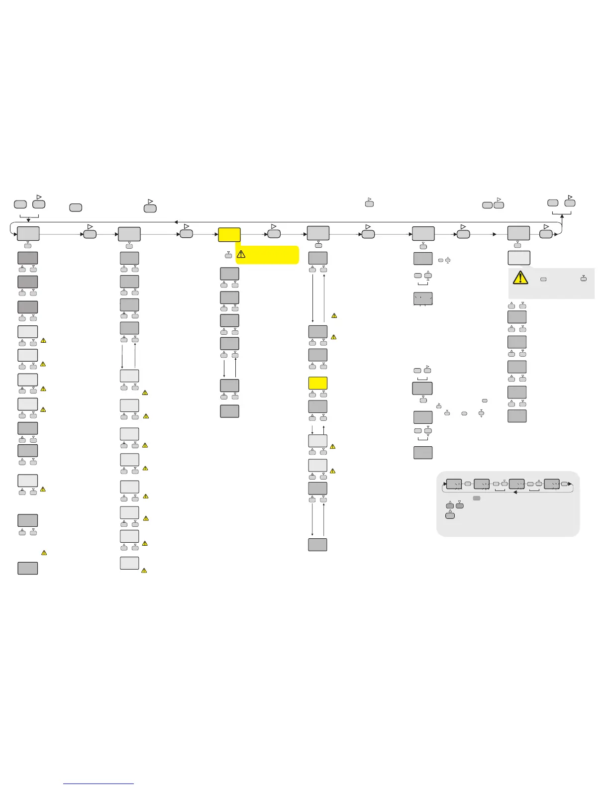
Parameter Setting Diagram
C.HyS.
5
C.HyS.
6
SET
SET
C/A SET
C/A SET C/A SET C/A SET
SET
C/A SET
C.HyS.
6
When holding key, the value of parameter flashes and using
keys the requested value can be adjusted.
If key is pressed and held 0.6 seconds, the value of the selected
parameter changes rapidly. If waited enough,the value increases 100 at each
step. After 1 second following the release of the key, initial condition is
returned.The same procedure is valid for the decrement key.
2/7
C.typ
HEAt
C.typ. = Control output type
C.typ. = HEAt means heating control.
C.typ. = CooL means cooling control.
ETxx20-EN-01-170816

 Loading...