9
10
6
8
ET4420
ET7420
ET8420
ET4420
ET7420
ET8420
ET9420
ET4420 ET7420
ET8420 ET9420
10
9
10
9
10
12
11
11
12
10
9
10
8
ET9420
8
9
9
10
8
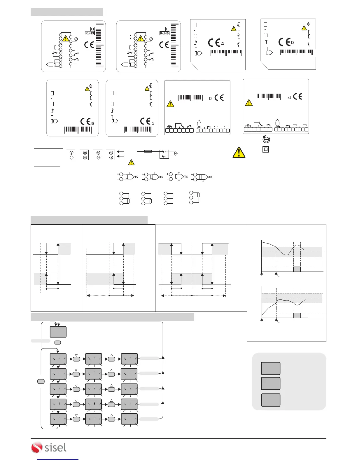
CONNECTION DIAGRAM
NOTE :
SUPPLY VOLTAGE
F 100 mA
250V AC
230V AC or 24V AC
Supply
Cable Size : 1,5mm²
Line
Neutral
Fuse should
be connected.
Switch
184-253V AC
50/60Hz 7VA
SENSOR INPUT:
For J - K - T- S and R Thermocouples :
Use the correct compensating cable.
Do not make any supplement to cables. Connect
the thermocouple cables to the right places at the
input terminal.
Logic output of the instrument is not electrically
insulated from the internal circuits. Therefore, when
using a grounding thermocouple, do not connect the
logic output terminals to the ground.
1) Mains supply cords shall meet the requirements of
IEC 60227 or IEC 60245.
2) In accordance with the safety regulations, the power
supply switch shall bring the identification of the
relevant instrument and it should be easily accessible
by the operator.
Note :
Holding screw
0.4-0.5Nm
Equipment is protected throughout
by DOUBLE INSULATION.
PT100
PT100
PT100
PT100
ALARM1 AND ALARM2 OUTPUT TYPES
Independent Alarm
A1.tp.=indE
Deviation Alarm
A1.tp= dE.
Band Alarm
A1.tp.= bAnd
A1.St.= Hi
A1.St.= lo
A1.St.= Lo
A1.St.= Hi
ASV
SV
SV
SV
SV+ASV
SV+ASV
SV-ASV
OFF
OFF
OFF
OFF
OFF
OFF
-300
300
+300
300
ON
ON
ON
ON
ON
ON
SV = CONT output set value ASV = Alarm output set value
(ASV min. =-300, ASV maks. = +300)
(ASV min. = 0, ASV max. = +300)
(ASV min. = beginning of scale
ASV max. = end of scale)
SV =CONT output set value ASV = AL1 output set value
a1,Hy
A1.Hy
A1.Hy
A1.Hy
Band Alarm With Inhibition
A1,tp.= bAn.i
ON
ON
OFF
OFF
Beginning
SV =Set point of CONT output
ASV = Set point of AL1 output
(ASV min. = 0, ASV max. = 300 )
Band alarm is possible
Band alarm is possible
Beginning
SV
SV
SV+ASV
SV+ASV
SV-ASV
SV-ASV
SET
C/A SET
250
400
C1.SE.
400
C2.SE.
400
a1.SE.
500
a2.SE.
500
m.SEt
50
C1.SE.
400
C2.SE.
400
a1.SE.
500
a2.SE.
500
m.SEt
50
C1.SE.
399
C2.SE.
399
a1.SE.
499
a2SE.
499
m.SEt
49
SET
C/A SET
SETTING UP ALARM CONTROL AND SETPOINT VALUES
3 seconds later
3 seconds later
3 seconds later
3 seconds later
3 seconds later
3 seconds later
For resistance (PT100) Sensor :
When using 2-wire PT100 sensor, as shown in the
figures, make 8 and 9 terminals short circuit for
ET4420, ET7420 and ET9420 devices, make 10 and 11
terminals short circuit for ET8420 devices.
If the C.O.SE. parameter is set to SSR out,
this parameter is seen.
If one of the d.in.c. or f.kE.c. parameters are
set to the C2.S.A. value, this parameter is seen.
If one of the d.in.c. or f.kE.c. parameters are
set to the mAnu. value and if C. Pb is different
from 0, this parameter is seen.
ERROR MESSAGES
pfa
400
400
____
400
----
Temperature sensor
is broken.
Temperature value is
higher than the scale.
Temperature value is
broken or over temperature.
3/7
ETxx20-EN-01-170816
SİSEL MÜHENDİSLİK ELEKTRONİK SAN. VE TİC. A.Ş.
Şerifali Mah. Y.Dudullu 34775
ÜMRANİYE/İSTANBUL-TURKEY
Tel : +90 216 499 46 64 Pbx. Fax : +90 216 365 74 01
url : www.enda.com.tr
Barbaros Cad. No:18
ENDA
TM
ENDA
INDUSTRIAL ELECTRONICS
ET7420 - 230VAC - RS
PID TEMPERATURE CONTROLLER
230V AC +10% -20%
50/60Hz 7VA
C / A2
AC 250V 8A
RESISTIVE
LOAD
A1
AC 250V 8A
RESISTIVE
LOAD
11
12
13
14
15
16
17
SN: XXXXXXXXX

 Loading...