OxyMax W COS 41 4 Wiring
Endress+Hauser 13
4Wiring
4.1 Direct connection to the transmitter
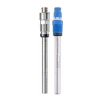
The sensor COS 41 is connected using a special measuring cable. The wiring diagram
is contained in the Operating Instructions of the transmitter Liquisys M COM 223/253-
DX/DS
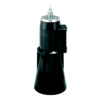
4.2 Connection via the junction box VBM
To lengthen the sensor connection beyond the length of the fixed cable, you require a
junction box VBM. The connection is lengthened to the transmitter using the special
measuring cable CYK 71.
Figs. 4.1 and 4.2 show the junction box VBM with its dimensions. The special measuring
cable CYK 71 is depicted in Fig. 4.3. Please refer to it for information on the terminals
and their assignment for connection to the transmitter. The interior white and yellow pilot
wires have no function.
Special measuring cable
CYK 71
Fig. 4.4 on page 14 is a schematic diagram of the sensor connection to the junction box
VBM.
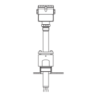
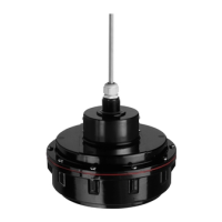
Fig. 4.1: Junction box VBM, side view Fig. 4.2: Junction box VBM , p lan view
54
26,8
C07-COS41xxx-04-05-01-xx-001.EPS
136
52
80
Pg 13,5
113
125
62,5
10
C07-COS41xxx-04-05-03-xx-001.EPS
Terminal Assignment
S Outer screening
12
Active inner screening
(NTC temperature sensor)
90 Cathode
91 Anode
11 NTC temperature sensor
Fig. 4.3: Special measuring cable CYK 71
BR
GN
WH
RD
C07-COS41xxx-04-05-00-de-001.EPS
 Loading...