Do you have a question about the Endress+Hauser Liquipoint FTW 31 and is the answer not in the manual?
Explanation of how the alternating voltage between probes detects liquid levels.
Overview of system setups with integrated and separate electronic inserts.
Details on the FEW 52 insert, its output signal, and fail-safe modes.
Information on the FEW 54 insert, relay output, and associated settings.
Specifications for the FEW 58 insert, NAMUR output, and fail-safe operation.
Detailed description of the FEW 54 relay output circuit and load handling.
Detailed description of the FEW 58 NAMUR output circuit and signal transmission.
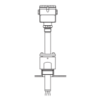
Detailed drawings showing dimensions for rod and rope probe versions.
Guide to selecting the correct product code for FTW 31 based on features.
Guide to selecting the correct product code for FTW 32 based on features.
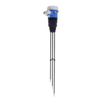
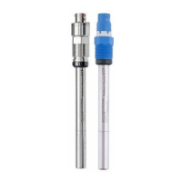
The Liquipoint T FTW 31 and FTW 32 are level limit switches designed for multiple point detection in conductive liquids, with conductivity starting from 10 µS/cm. These devices are suitable for various applications such as overspill protection, dry running protection, two-point control of pumps, and general multiple point detection within an existing process connection.
The measuring principle relies on an alternating voltage applied between the rod probes in an empty tank. When a conductive liquid connects the ground probe rod with a maximum probe rod, a measurable current flows, causing the Liquipoint T to switch. For level limit detection, the device switches back once the liquid clears the maximum probe. In two-point control, the Liquipoint T only switches back after both the MAX and MIN probes are cleared. The use of alternating voltage prevents corrosion of the probe rods and electrolytic destruction of the product. The system is designed as a closed, potential-free circuit between the probe rods and the electronics, making the tank wall material irrelevant for measurement. The probe rods are safe to touch during operation.
The measuring system can consist of FTW 31 or FTW 32 with two or three rods/ropes and an integrated electronic insert, or it can be a separate-instrument version without an integrated electronic insert, requiring connection to external control units like Nivotester FTW 325 or FTW 470 Z. The compact-instrument version with three probes or rods always operates in "As" mode. For multiple point detection, the separate-instrument version can accommodate up to five rods or ropes, requiring two Nivotester FTW 325 or FTW 470 Z units.
FEW 52 (DC-PNP):
FEW 54 (Relay):
FEW 58 (NAMUR):
| Manufacturer | Endress+Hauser |
|---|---|
| Application | Level detection in liquids |
| Material | Stainless steel, PTFE |
| Process Connection | Threaded, Flanged |
| Protection Rating | IP68 |
| Output | PNP |