Gas Heat - Ninth Edition, September, 2018 7
INSPECTION OF FLUE CONNECTIONS
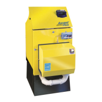
The SYSTEM 2000 boiler burns gas and produces combustion products that must be vented outside the house
or building.
For chimney installations, there will be a flue pipe connecting the flue outlet of the boiler to the base of the
chimney. The flue pipe connections will be under positive pressure for a few seconds each time the boiler
starts, until negative draft has been established due to hot air rising up the chimney.
Once a month, inspect the flue pipe and connections. Look for evidence of deterioration from corrosion or other
sources. Watch the flue pipes during a start up of the boiler and look and smell for evidence of escaping flue
products.
For a chimney installation particularly examine the joint between the boiler outlet and the flue pipe. Also
examine the joint between the flue pipe and the base of the chimney.
DIGITAL MANAGER OPERATION AND DIAGNOSTICS
o To confirm operation of the Manager lights, turn power off briefly and power up the Manager. On startup, all
outputs and temperature lights should turn on for a brief moment.
o Thermostat Lights indicate a thermostat calling for heat. If all lights are OFF, the burner will not run because there
is no call for heat. T
4
is located on the bottom.
o The digital temperature sensor senses return temperature and is required for the Manager to work properly. The
E100 error code will flash if the digital sensor is not working properly.
o The Option Switches located on the underside of the Manager are used to customize system settings.
o Heating or Zone output lights indicate 24-volt power from 24VAC to Z
X
(Z
HW
, Z
1
, Z
2
, Z
3
, and/or Z
4
). This provides
power to 24-volt zone valves or zone circulator relays.
o The Inducer light ON indicates 24 volts from IND to 24VAC. This pulls in the 24-volt coil on the inducer relay,
providing 120-volts to the power vent. This will only operate with option switch 2 ON.
o The Burner light ON indicates a closed contact between B
1
to B
2
. This is wired to T-T on the burner primary
control.
o Burner Restart Delay: If a thermostat light goes off, ending a call for heat, and then immediately goes back on,
calling for heat again, the Manager will delay turning on the burner light for two minutes to prevent short-cycling
the burner. (45 second delay for a Zone HW call.)
o The Circulator light ON indicates 24 volts from CIRC to 24VAC. This pulls in the 24-volt coil on the Burner/Main
circulator relay, providing 120-volt power to both the main circulator and the burner.
o The temperature display bar graph indicates the temperature of the water returning to the boiler, not the
temperature of the water being supplied to the heating system from the boiler.
o The Manager is the operating aquastat and will turn off the burner if return temperature reaches 170°F (operating
limit).
o The zone outputs will open when the return temperature is above 150°F and zone outputs will close when the
return temperature drops below 130°F. If a new zone calls when the returns are below 150°F the new zone will
not open until the temperature exceeds 150°F (even if other zones are open).
o The boiler will typically take about 2 minutes to reach 150°F from a cold start.
o When the Manager is working properly and has found a condition that needs service, the 100,120,130, or 140
light will flash. Flashing lights mean the boiler, circulator, or something other than the Manager needs service.
o NOTE: The Manager cannot lockout the primary control on the burner. The E140 error code usually indicates
that a burner lockout has occurred. Follow the instructions under ‘In Case Of No Heat’ in order to reset the burner
control.

 Loading...