2
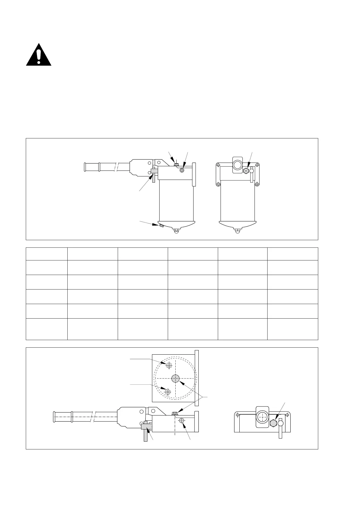
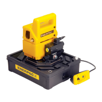
FIGURE 1 PL-3007R PL-2509R PL-2011R PL-1317R PL-1025R
A Release valve Release valve Release valve Release valve Release valve
B Outlet port G1/4" Outlet port G1/4" Outlet port G1/4" Outlet port G1/4" Outlet port G1/4"
C Pressure relief cap Pressure relief cap Pressure relief cap Pressure relief cap Pressure relief cap
D Filler cap Filler cap Filler cap Filler cap Filler cap
E Filler cap and oil Filler cap and oil Filler cap and oil Filler cap and oil Filler cap and oil
sight gauge sight gauge sight gauge sight gauge sight gauge
Figure 1 PL-R
WARNING: These pumps operate with a
vented reservoir. You should therefore
ensure that the reservoir is provided with
a breather hole. If you do not, there is a
risk that the pressure in the reservoir will become
too high, and an explosion can occur. This can lead
to injury and/or material damage. Try to make sure
that the amount of oil fed to the reservoir NEVER
exceeds the amount of oil that the reservoir can
comfortably hold.
3.0 DESCRIPTION
PL R-series models
In figure 1 below and in the accompanying table you
will find the most important parts of the PL R-series
hand pump. The purpose of the pressure relief cap
is to relieve the pressure in the reservoir should this
inadvertently build up to an unacceptable level.
PL F-series models
In figure 2 below and in the accompanying table you
will find the most important parts of these models of
hand pumps.
Figure 2 PL-F
Suction port
Return to tank


 To Next Page