2
WARNING: Only use hydraulic torque wrenches in a
coupled system. Never use a torque wrench with
unconnected couplers. If the torque wrench becomes
extremely overloaded, components can fail catastrophically
causing severe personal injury.
IMPORTANT: Hydraulic equipment must only be serviced
by a qualifi ed hydraulic technician. For repair service,
contact the Authorized ENERPAC Service Center in your
area. To protect your warranty, use only ENERPAC oil.
WARNING: Immediately replace worn or damaged parts
with genuine ENERPAC parts. Standard grade parts will
break causing personal injury and property damage.
ENERPAC parts are designed to fi t properly and withstand high
loads.
WARNING: Do not use electric pumps in an explosive
atmosphere. Adhere to all local and national electrical
codes. A qualifi ed electrician must do installation and
modifi cation.
WARNING: Keep hands clear of moving parts and
pressurized hoses.
WARNING: These pumps have internal factory adjusted
relief valves, which must not be repaired or adjusted
except by an Authorized Enerpac Service Center.
WARNING: To prevent damage to pump electric motor,
check specifi cations. Use of incorrect power source
will damage the motor.
3.0 SPECIFICATIONS
3.1 Performance Chart (see bottom of page)
3.2 Flow Chart (see Figure 1):
Flow and current vs. Pressure
Current (Amps)
Flow
in
3
/min
Current (Amps)
Flow (in
3
/min)
Pressure (psi)
115V
230V
0
5
10
20
25
15
100
200
300
400
500
600
700
00
0 1000 2000 3000 4000
5000
6000 7000 8000 9000 11,60010,000
Figure 1, Flow Chart
4.0 INSTALLATION
Install or position the pump to ensure that air fl ow around the
motor and pump is unobstructed. Keep the motor clean to
ensure maximum cooling during operation.
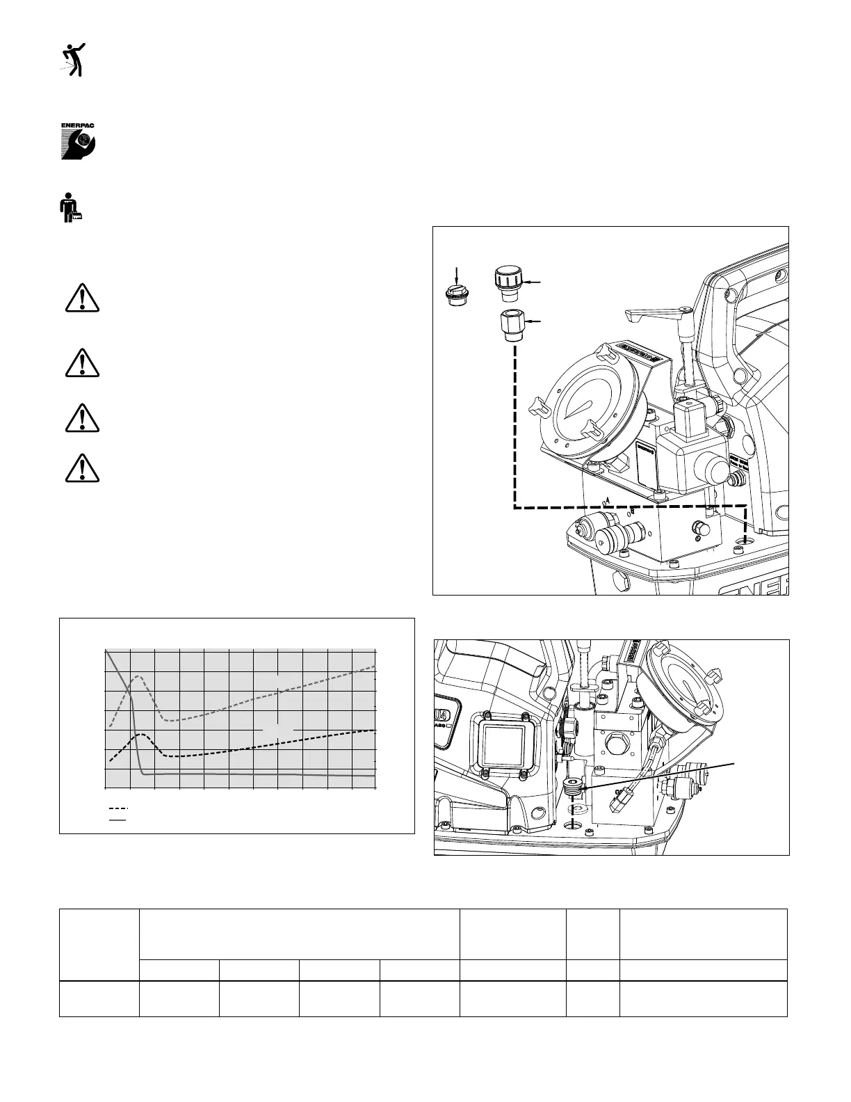
4.1 Breather Cap and Oil Fill Plug (See Figures 2 & 3)
A shipping plug (A) is installed in the breather port on the top of
the reservoir. Before using the pump, replace the shipping plug
(A) with the breather cap (B) and adapter fi tting (C). Note: The oil
fi ll port is located on the opposite side of the pump. The oil fi ll
port uses an SAE #10 plug (D).
A
C
B
Figure 2, Breather Installation
D
Figure 3, Oil Fill Plug
▼ ZU4 PERFORMANCE CHART
Motor
Size
Output Flow Rate
in
3
/min
Motor Electrical
Specifi cations
Sound
Level
Relief Valve
Adjustment Range
(hp) 100 psi 700 psi 5,000 psi 10,000 psi (Volts-Ph-Hz) (dBA) (psi)
1.7* 700 535 76 60
115-1-50/60
230-1-50/60
85-90
1,400-10,000 for “Q” version
1,400-11,600 for “E” version
*Actual power consumption depends on the application. See Figure 1.
 Loading...