2
1.1. Microprocessor-controlled
1.2. Able to auto identify battery’s capacity
1.3. Able to adapt to State of Charge (SoC)
1.4. Compatible with battery voltages of:
1ph 3ph
12V
24V 24/36/48V
36/48V 72/80V
96V
120V
1.5. Wireless integration with EnerSys
®
Wi-iQ
®
battery monitoring devices
1.6. Individual battery pack recognition and automatic pairing with the charger
1. 7. Unique prole for charging Thin Plate Pure Lead (TPPL)
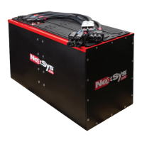
1.8. Unique proles for NexSys
®
battery charge applications: NXBLOC;
NXSTND; NXSFAST; NXP2V; NXPBLC.
1.9. Remote access via E Connect™ mobile app to change settings, monitor
charger and share data.
1.10. Controller Area Network (CAN) communication capable.
1.11. Fully programmable to unique eet requirements.
1.12. Battery chemistry agnostic - EnerSys® Lithium-ion (Li-ion), TPPL, Flooded
and Gel Lead Acid batteries.
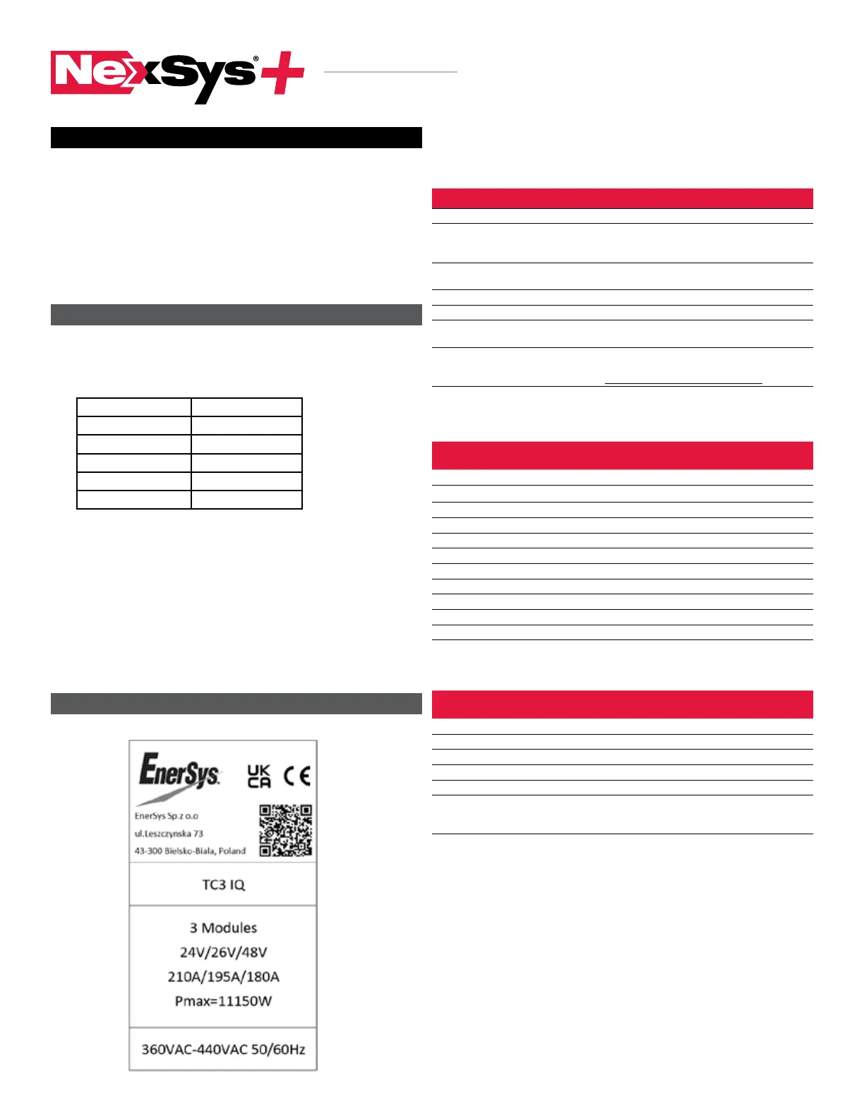
2.1. Name plate labels
2.1.1. Name plate label definitions
1. Features
TABLE OF CONTENTS
2. Technical Information
BATTERY CHARGER
INSTRUCTIONS FOR USE
Item Description
Serial Number Provides date code.
Hertz
Input voltage frequency. Under no conditions operate
the charger at a different frequency or from a generator
with unstable frequency.
Phase
TCX. When “1” indicates a Single Phase Charger
and “3” indicates a Three Phase Charger.
AC Volts Nominal voltage for which this charger is rated to operate.
DC Volts Nominal DC output voltage of the charger
Modules
Actual number of power modules installed
in the charger cabinet.
DC Amps
DC current that this charger will deliver
to a discharged battery with the number of power modules
installed and based on the Nominal Voltage
2.1.2. Output power letter codes
Output Power
(kW)
Number
Modules
Module Power
(kW)
1.0 1 1.0
2.0 2 1.0
3.0 3 1.0
3.5 1 3.5
7. 0 2 3.5
10.5 3 3.5
14.0 4 3.5
1 7. 5 5 3.5
21.0 6 3.5
24.5 7 3.5
28.0 8 3.5
2.1.3. Cabinet size (number of modules available) and DC cable size
Phases
Module
Positions
Standard
Cable Gauge
Comments
1ph Max 1 6 mm
2
Stand alone cabinet
1ph Max 3 25 mm
2
Three slot, 3 kW cabinet
3ph Max 2 35 mm
2
Two slot, 7 kW cabinet
3ph Max 4 70 mm
2
Four slot, 3.5 to 14 kW cabinet
3ph Max 6 95 mm Six slot, max 21 kW cabinet
3ph Max 8
70 mm or
1 x 95 mm
Eight slot, max 28 kW cabinet.
Dual cable for 24/36/48Vdc single
cable for 72/80Vdc
1. Features ...................................................................................2
2. Technical Information ..............................................................2
3. Safety Precautions .................................................................. 3
4. Installation ...............................................................................4
5. Operating Instructions ............................................................4
6. Menu and Display Information .............................................. 6
7. Service and Troubleshooting ..................................................7