ENFORCER Pushbutton Request-to-Exit Plates
4 SECO-LARM U.S.A., Inc.
The additional LED on the SD-7623-GSTQ serves as a status indicator. It may toggle between ‘off’ and
‘on’ (either red or green) or it may
toggle between ‘red’ and ‘green’. As a status indicator, it could
indicate that the lock has entered the timed unlock state after the button has been pressed. On doors
with a door position monitoring output, the status LED could indicate that the door is
the door is opened, returning to standby only after the door has been closed and/or relocked.
Follow the wiring instructions for the SD-7202GC-PTQ (see page 3).
Decide on the role of the status LED (see above):
a. For status LED off in standby mode (pushbutton LED on), turning on when button is pressed (with
pushbutton LED turning off), then returning to standby mode when timer delay ends (see Fig. 7):
i. Connect the red (for red LED) or green (for green LED) wire of the status LED to the timer
module’s N.O. relay output terminal (the other colored wire will be unused).
ii. Connect the black wire of the status LED to the timer module’s negative (–) power input.
b. For status LED (and pushbutton LED) normally on in standby mode, with status LED changing
colors when button is pressed, then returning to standby mode when timer delay ends (see Fig. 8):
i. Connect one red (or green) wire of the status LED to the timer module’s N.O. relay output
terminal.
ii. Connect the other colored wire of the status LED to the timer module’s N.C. relay output
terminal.
iii. Connect the black wire of the status LED to the timer module’s negative (–) power input.
A. When using a 24VDC power supply, a resistor (included) must be wired in-line with
the status LED’s black wire.
B. Suggested wiring assumes a single power supply (see Fig. 10). Timer module’s relay
output N.C. terminal must be connected to the controlled device’s power input
positive (+) terminal and timer module’s relay output COM terminal must be connect
to the power supply’s positive (+) terminal.
Set the time of the timer module between 1~180 sec via the trimpot (see Fig.6). Turn clockwise to
increase and counterclockwise to decrease. Test to ensure the timer is set correctly.
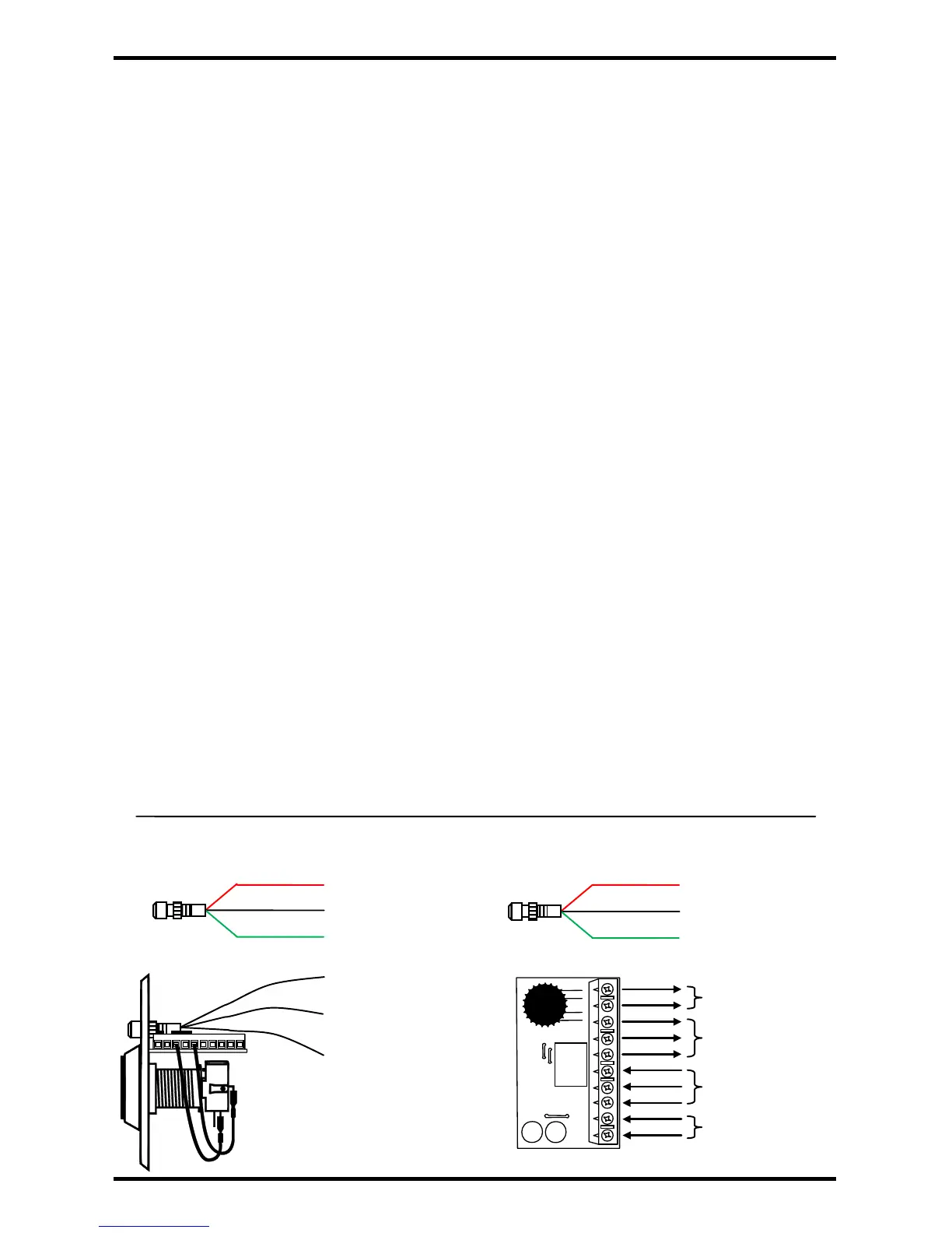
Wiring the SD-7623-GSTQ (with LED and timer module):
LED – Standby ‘Off’, Door Unlocked ‘Red’
LED Standby ‘Green,’ Door Unlocked ‘Red’
Timer Module Relay O/P N.O.
Figure 10 – Timer Module Top View
Note: Terminal legend can be found on back of PCB.
1
Use included resistor when connecting to 24VDC.
 Loading...