Step 3: Unbox and Mount the Enpower on the Wall
WARNING: Risk of injury. Take care when lifting. The Enpower is heavy 38.5 kg (85 lbs).
WARNING! Risk of injury and equipment damage. Avoid dropping the Enpower. Doing so
may create a hazard, cause serious injury, and/or damage the equipment.
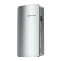
A. Remove the lid from the Enpower box, and locate the slots on both sides of the Enpower
enclosure.
B. Locate the lifting handles (sold separately) and check
that the plungers are extended and ready to engage
into the Enpower slots.
C. Align one handle on one side of the Enpower and
press the handle into the slots, and slide the handle
toward the top of the Enpower enclosure until it clicks
into place. Check that the handle is secure.
D. Repeat on the other side with the second handle.
WARNING! Risk of injury and equipment
damage. Two persons are required to lift the
Enpower.
E. Use the lifting handles, take the Enpower from the packaging, making sure it is top side up
(upright). Enpower is designed only for vertical installation without inclination (must be level).
F. Lift the Enpower slightly above the installed wall mount bracket and allow it to slide down so that
the bracket facing hooks set into both the top and bottom shelves of the wall mount bracket.
G. Allow the Enpower to slide down until the Enpower is fully seated on the wall-mount bracket shelf.
WARNING! Risk of injury and equipment damage. Do not
release the Enpower until you ensure that the Enpower is fully
seated in the wall-mount bracket shelf.
H. For each handle, pull the plunger tabs to release them and remove
the lift handles.
I. Reserve the handles for the next installation.
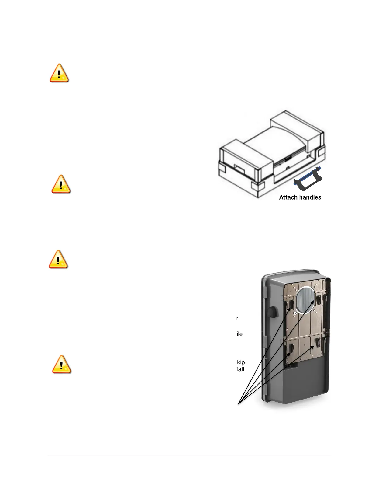
J. On the bottom handle mounts, use the two provided partial-
threaded custom M6 screws to secure each side of the Enpower
and tighten to 0.5 N•m (4.4 lb•in) or less.
The threaded portion of the screw engages with the bracket, while
the unthreaded portion of the screw engages with the hole in the
bracket to prevent vertical movement of the bracket.
WARNING! Risk of injury and equipment damage. Do not skip
this step. Without these screws in place, the Enpower may fall
and cause injury or damage if bumped or shaken.
K. Use the four filler plates, provided in the lit kit,
to cover the screws.