QUICK INSTALL GUIDE - PHILIPPINES
Installing the Enphase Envoy-S Metered
To install the Enphase Envoy-S Metered™ gateway with integrated meter, read and follow all warnings and instructions in this Guide
and in the Enphase Envoy-S Installation and Operation Manual at: enphase.com/philippines. Safety warnings are listed on the back
of this guide.
PREPARATION
A ) Download the latest version of the Enphase Installer
Toolkit mobile app and open it to log in to your Enlighten
account. With this app, you can connect to the Envoy-S
to track system installation progress. To download, go to
enphase.com/toolkit or scan the QR code at right.
B ) Check the box for the following items:
•
Enphase Envoy-S Metered gateway
•
Two split-core current transformers (CTs) for production and
consumption metering
•
Length of DIN rail for mounting
•
Ferrite bead to attach to your Ethernet Cable, if used
• Quick Install Guide (this document)
C ) Check that there is enough space in the switchboard to install CTs.
Do not install the CTs in a panel where they exceed 75% of the wiring
space of any cross-sectional area within the panel.
D ) Install the Envoy-S Metered in an IP54-rated, or better enclosure with
conduit attachment when installing outdoors. Do not drill holes on
the top of the enclosure or anywhere that allows moisture ingress.
Metallic enclosures may impair Wi-Fi signal strength. Use an appro-
priately rated enclosure if installing the Envoy-S indoors.
E ) If you are installing the Envoy-S in a multi-phase application, make
sure you have the following items:
•
Additional CTs (CT-100-SPLIT) for multi-phase installations. Make
sure you have one CT for each phase monitored, for both produc-
tion and consumption.
•
A phase coupler. If installing on a 3 phase site, install a phase
coupler on the load side of the over-current protection device. See
the Technical Brief on Phase Coupling for your region at enphase.
com/support. Consult Enphase support for compatible devices.
F ) Decide how to connect the Envoy-S to the Internet: choose to use
Wi-Fi, an Enphase Mobile Connect modem, or Ethernet.
G ) Make sure you have the following optional items, if needed:
•
Enphase Mobile Connect™ modem (order CELLMODEM-02)
•
Ethernet over power line communication (PLC) bridge with Ether-
net cables [order EPLC-02 (EU), EPLC-03 (UK) or EPLC-04 (AU/NZ)]
•
Ethernet cable [802.3, Cat5E or Cat6, unshielded twisted pair
(UTP)]. Do not use shielded twisted pair (STP) cable.
H ) Install the PV system as directed by the installation manuals.
I ) If an Enphase PV system is or will be installed at the site, create a
paper installation map to record device serial numbers and positions
in the array. You will scan this map later using Installer Toolkit and
your mobile device.
•
As you did with the microinverters (and Enphase AC Batteries, if
installed), peel the removable label from the bottom of the Envoy-S
and afx it to the paper installation map.
•
Always keep a copy of the installation map for your records.
NOTE: If needed, you can nd an installation map with any Enphase
Microinverter Quick Install Guide.
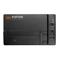
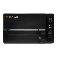
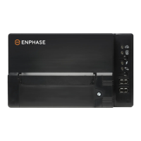
(Model ENV-S-AM1-230-60)
Envoy-S Display and Controls
Network Communications LED
Green when Envoy-S is
connected to Enphase Enlighten™.
AP Mode LED
Green when Envoy’s AP Wi-Fi
network is available.
AP Mode Button
Press to enable Envoy’s AP Mode
for connecting with a mobile device.
Hold for 5 seconds to start WPS
connection to a router.
Power Production LED
Green when microinverters are
producing power.
Device Communications LED
Green when devices are
communicating with Envoy-S.
Device Scan Button
Press to start/stop 15 minute scan for
devices over the power line.
Track system installation progress with the Enphase Installer Toolkit™
mobile app. The LEDs on the Envoy-S are solid green when a function is
enabled or performing as expected, ashing when an operation is in
progress, or solid red when troubleshooting with Installer Toolkit is
required. For a legend of all LED states, see Troubleshooting
a
.
Enphase Installer
Toolkit mobile app
How It Works
POWER LINE
COMMUNICATIONS
NETWORK
COMMUNICATIONS
Microinverters
Envoy-S
Switchboard
Router
Enlighten
To Internet
Enphase Customer Support: http://www.enphase.com/philippines
SAFETY
Safety and Advisory Symbols
DANGER: This indicates a hazardous situation, which if not avoided,
will result in death or serious injury.
⚠
WARNING: This indicates a situation where failure to follow instruc-
tions may be a safety hazard or cause equipment malfunction. Use
extreme caution and follow instructions carefully.
✓
NOTE: This indicates information particularly important for optimal
system operation. Follow instructions carefully.
Safety Instructions
DANGER: Risk of electric shock. Risk of re. Do not attempt to repair
the Envoy-S; it contains no user-serviceable parts. Tampering with
or opening the Envoy-S will void the warranty. Warranty void if cover
removed. If the Envoy-S fails, contact Enphase Customer Support for
assistance (http://www.enphase.com/philippines).
DANGER: Risk of electrocution! Do not install CTs when current is
owing in the sensed circuit. Always install CT wires in the terminal
blocks before energising the sensed circuit.
DANGER: Risk of electric shock. Do not use Enphase equipment in a
manner not specied by the manufacturer. Doing so may cause death
or injury to persons, or damage to equipment.
DANGER: Risk of electric shock. Be aware that installation of this
equipment includes risk of electric shock. If you wire the Envoy-S at
the sub-board, always de-energise the sub-board before beginning.
DANGER: Risk of electric shock. Risk of re. Only qualied personnel
should troubleshoot, install, or replace the Envoy-S.
DANGER: Risk of electric shock. Risk of re. Do not wire unused termi-
nals or terminal blocks on the Envoy-S.
⚠
WARNING: Before installing or using the Envoy-S, read all instructions
and cautionary markings in the technical description and on the
Envoy-S.
⚠
WARNING: Risk of equipment damage. If installing the Envoy-S in an
enclosure, choose area for installation where ambient temperature
does not exceed 46º C.
✓
NOTE: Do not install the CTs in a panel where they exceed 75% of the
wiring space of any cross-sectional area within the panel, or refer to
local standards for guidance.
✓
NOTE: Perform all electrical installations in accordance with all nation-
al and local electrical codes.
✓
NOTE: To ensure optimal reliability and to meet warranty require-
ments, the Enphase Envoy-S must be installed according to the
instructions in this guide.
TROUBLESHOOTING
a
LED overview
LED State Description
All
Flashing red in unison
The Envoy-S is booting up
Flashing green sequentially Software upgrade in progress
Network
communica-
tions
Solid green Communicating with Enlighten
Flashing green WPS connection in progress or the Envoy-S
is attempting to connect to Enlighten
Solid red
Local network connection only
Off No network connection
AP mode
Solid green AP mode enabled:
Envoy-S Wi-Fi network available
Off AP mode disabled:
Envoy-S Wi-Fi network unavailable
Power
production
Solid green All communicating microinverters are
producing
Flashing green Microinverter upgrade in progress
Solid Red
At least one microinverter is not producing
Off Microinverters are not producing or com-
municating (low light or night time)
Device
communica-
tions
Solid Green All devices are communicating
Flashing Green Device scan in progress
Solid Red
At least one device is not communicating
Off Devices are not communicating
(low light or night time)
b
Device detection issues
If the Device Communications LED lights solid red, it may be a result of low light
levels. If there isn’t enough sunlight to power up the microinverters, they can’t commu-
nicate with the Envoy.
If there is sufcient daylight for the microinverters to power up, the issue may be that
the Envoy-S is having difculty communicating over the power lines. To troubleshoot
this issue:
•
Check the Installer Toolkit mobile app to see which devices are not
communicating.
•
Check that the circuit breaker(s) for the PV array are in the “ON” position.
•
Verify that the PV modules are connected to the microinverters.
•
Verify the PV module DC voltage is within the allowable range for the microinverter.
c
Power production issues
If the Power Production LED lights solid red, check the Installer Toolkit mobile app
to see which microinverters are not producing:
•
If none of the microinverters are producing power, there may be a grid or wiring
issue. First, verify that there is proper input voltage and frequency from the grid.
Next, check the breaker and wiring, starting at the switchboard.
•
If all of the non-productive microinverters are on the same branch, check the
breaker and wiring starting at the junction box for the affected branch.
•
If only one or scattered microinverters are not producing power, rst check to see
that the AC connectors are fully seated in the Engage Cable connectors. Next,
check that each module is providing the required startup voltage for the micro-
inverter (22V). A PV module that is failing or that is undersized may not generate
enough power for AC conversion.
d
Internet connection issues
If you are using Wi-Fi and the Network Communications LED remains off:
•
The WPS connection window may have timed out. Retry the connection steps.
•
Make sure that the broadband router is operational by checking that other devic-
es at the site can access the network.
•
Be aware that metal enclosures or obstructions impede wireless communication.
•
If you cannot see your router or access point in the list on the Envoy, or cannot
maintain a connection, it may be necessary to add a wireless repeater to extend
the network range.
If you are using Wi-Fi and the Network Communications LED lights solid red, make sure
that the broadband router is connected to the Internet by checking that other devices
at the site can access the Internet.
If you are using the Enphase Mobile Connect modem and the Network Communica-
tions LED remains off or lights solid red, see Troubleshooting in the Enphase Mobile
Connect Installation Guide.
For any connection method, you can troubleshoot network issues with the Installer
Toolkit mobile app by tapping the Network button, then Diagnostic Tools.
If you replace the broadband router, congure the Envoy-S Wi-Fi settings for the new
Wireless Network Name (SSID) and password.
© 2021 Enphase Energy. All rights reserved. Enphase, the Enphase logo, Enphase IQ 7, Enphase IQ 7+, Enphase IQ Battery,
Enphase Enlighten, Enphase IQ Envoy, and other trademarks or service names are the trademarks of Enphase Energy, Inc. Data subject to change. 2021-05-31