A) Before running the CT wires through conduit, use coloured tape to
mark each of the CTs and the free ends of its wires, marking each
with a different colour. You can run multiple CT wires through a
single conduit.
B ) Wire the Envoy-S for power
•
Depending on the number of phases you will wire, use a one-, two-,
or three-pole (20 A maximum) circuit breaker for the supply wiring.
•
Make sure supply wiring is 2.5mm
2
copper rated at 75º C or better.
•
Locate the screw on the terminal block door, and loosen it with a
screwdriver to unlock the door and ip it open.
•
Connect Line 1 to L1, Line 2 to L2, Line 3 to L3, and Neutral to N, as
required.
•
Tighten all connections to 0.56 Nm.
C ) Install the production CTs on phases as required:
•
Locate the arrow on the CT label.
•
To monitor production on Line 1:
-
Connect the white wire to the “I1•” terminal and the blue wire to
the “I1” terminal.
-
Clamp the CT on active Line 1 of the solar production circuit with
the arrow pointing toward the load (away from the solar array).
•
Tighten all connections to 0.56 Nm.
D )
Install the consumption CTs on phases as required:
•
Locate the arrow on the CT label.
•
Make sure that the AC mains wire(s) are de-energised until you
have secured the CT wires in the terminal blocks.
Note: Only run active conductors of the same phase through each
CT. Each CT can monitor multiple active conductors.
•
To monitor consumption on Line 1:
-
For the rst CT, connect the white wire to “I1•” and the blue wire
to “I1”.
-
Clamp the CT on the main supply Line 1 (active). When the
consumption CT is on Line 1 (active) conductor, the arrow must
point towards the load (away from the grid).
•
Tighten all connections to 0.56 Nm.
NOTE: Because of variance in switchboard design and main power
feed, there may not always be enough space to install CTs.
NOTE: It is important to match CT and voltage sense phases. Be
sure to consistently identify all the AC lines at three points: the main
switchboard feed, the Envoy, and the solar production circuit breaker.
Wire colours may not always consistently identify Lines 1, 2 and 3. If in
doubt, use a multimeter to check.
DANGER! Risk of electric shock. Always de-energise circuits
before wiring for power and CTs.
DANGER! Risk of electrocution! Do not install CTs when current
is owing in the sensed circuit. Always install CT wires in the
terminal blocks before energising the sensed circuit.
WIRING INSTRUCTION SHEET FOR PHILIPPINES
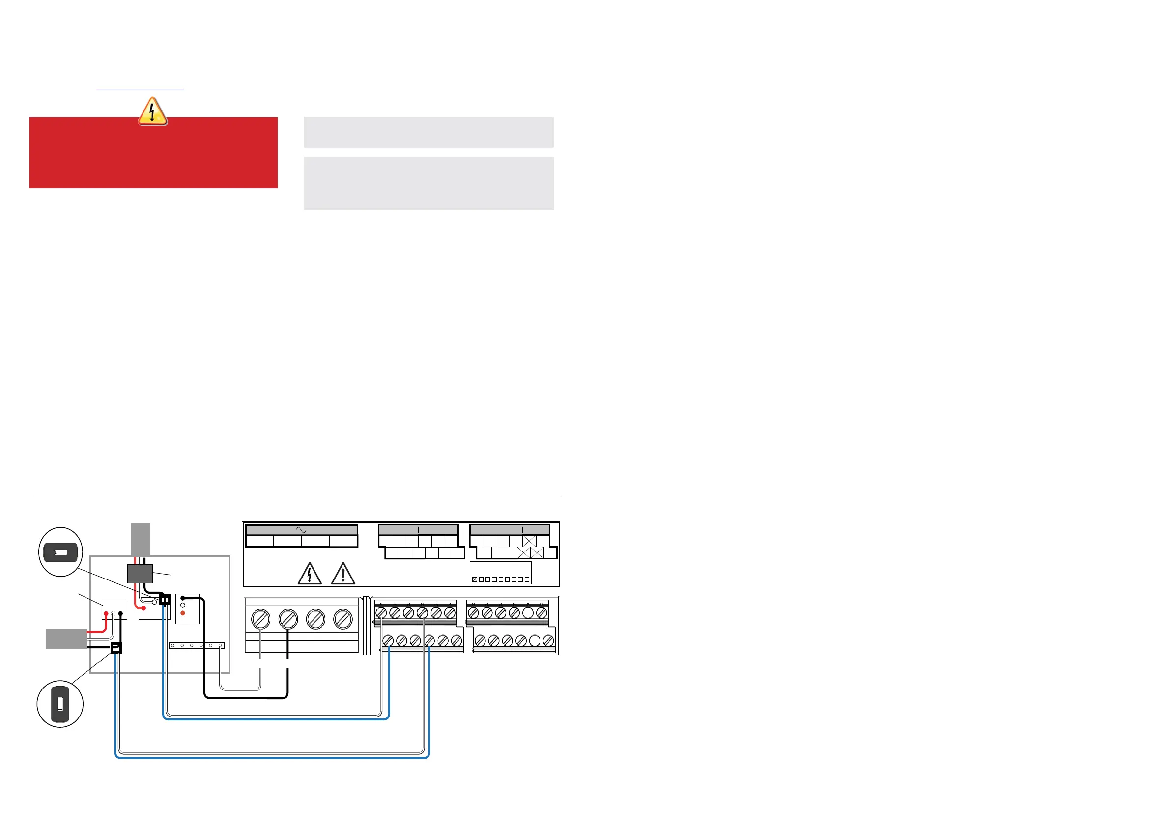
The Envoy-S uses term
inal blocks for power and metering connections. Wire these terminal blocks as described in the following.
You will need to install one split-core CT per monitored phase for production metering and one split-core CT per monitored phase for consumption metering. Use
a protected route in conduit (raceway) for the CT wires to the Envoy-S. If you need to extend the leads (up to 148 meters), refer to the Enphase Envoy-S Installation and
Operation Manual at: enphase.com/philippines.
Envoy-S Terminal Block
Switchboard
Output from
PV System
Main isolator
switch
Central disconnect
(contactor)
I1●
I1
I2●
I2
I3●
I3
I1●
I1
I2●
I2
I3●
I3
1 / 5 2 / 6 3 / 7 4 / 8
NO
RefGen
Com / DRM Ø
C
Production Consumption Digital Input Relay
PD, B300
OVC II
CU, 2.5 mm
2
, 75C
MEAS CAT III
OVC III
L1 L2
L3
N
0
1
2
3
4
5
6
7
8
AU/NZ: DRM Port
To meter
Production
CTs
Consumption
CTs
UP TO 250 Vac.
100A 0.5V 45-66Hz
UP TO 250 Vac.
100A 0.5V 45-66Hz
N
L1
 Loading...