6
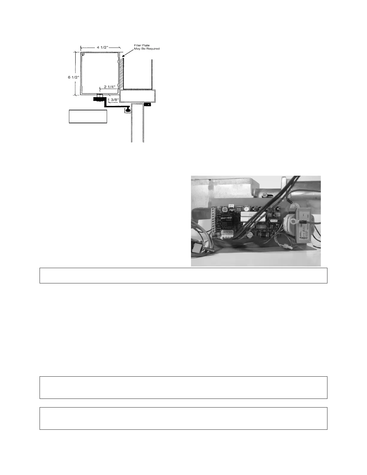
Double Egress Header
Due to double egress operators having (1) PULL type and (1) PUSH Type operator in the same housing
the header must be mounted 1 3/8” above the doorframe. Furthermore, arm clearance issues for the
PUSH type operator may arise. To insure the arm clears any existing doorstops please mount the arm
according to Option 1 under Push Arm Installation.
Motor Drive Installation
Lift the drive unit into position inside the mounted
body portion of the header. Install the back pair of
mounting ¼” X 20 NC ¾ “machine screws to secure
the unit in place. The control board is now placed in
the header and connect the motor wire leads (large
four pin) as well as the back check and latch wire
lead (small three pin) to the top of the board. The
control is anchored inside the header casing by a
supplied Velcro patch. Motor is plugged in the top
position for right hand swing, bottom position for left
hand swing. (LEFT HAND SHOWN)
WARNING: If the motor is not plugged into the circuit board there is no motor resistance against
the spring, when manually opening the door. The door or arm will close very quickly if opened.
Electrical Connection
Electrical power can now be safely supplied to the HA/FA-8 operator. The 115±5VAC supply lines are
connected to the black primary wires coming from the transformer and the ground wire is attached to
the operator header box. Mount the power switch by drilling a hole in the header to the latch side of the
unit.
The controller board settings have been pre-set prior to shipment. Adjustment information is detailed on
page 16. It will be necessary for the door operator to be functional while adjustments and settings are
made. A grey push actuator is mounted on the upper left corner of the circuit board to ease in the
adjustment process. Power up the unit and push an activating device and check to make sure that the
splined pinion drive rotates in the correct direction.
NOTE: THE GROUND WIRE FOR THE INCOMING 115±5VAC POWER AND THE SYSTEM GROUND
WIRE CANNOT SHARE THE SAME GROUNDING STUD. GROUND THE INCOMING 115±5VAC
ACCORDINGLY.
Note: installation of any extra wiring for controls or accessories into the header unit shall be
secured out of the way of all moving parts and any sharp edges that may cut into the outer
chasing of the wires.
-2 screws should be used at
either end (1/2" in from end
plate) to fasten directly to the
doors vertical jambs.
-2 more screws fasten the Header
Body to the bottom of the
doorframe approx. 10" in from
either end. The header body
should be able to support a
minimum of 200 lbs.



 To Next Page