7
ARM ASSEMBLY INSTALLATION
Push Arm Installation
1. To lock the drive from returning to the closed position manually rotate the drive coupler until a ¼
“X 20 NC threaded hole is exposed through the cast housing coupler window (figure 4 A&B).
Thread a provided machine screw in this hole. Now slide the door arm on the main spline pinion
and rotate (this may require multiple rotations) until the stop block engages the casting stopper
lug. The spring is now fully loaded.
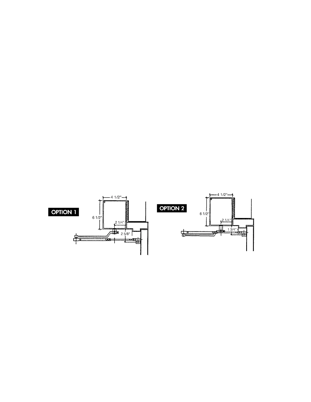
2. Install the arm component consisting of door shoe and adjustable rod on door; there are three
configurations available (Option 1-2-3). The first hole on door shoe should be 14” from the
doorframe for standard pivot doors.
3. Install the cast arm on pinion spline so that arm is protruding from header box at slightly more
than 90 degrees (closer to face of door). Insure arm will not come loose by using the provided ¼”
fender washer and ¼ X 20 NC dome head machine screw.
4. Position the rod alongside the sleeve and mark the cut line on the rod 1-1/2” past the second set
screw.
5. Remove door shoe and rod assembly. Cut rod. Reattach cut rod and shoe assembly.
6. Insert cut rod into sleeve and tighten setscrews.
7. Take completely assembled arm off pinion spline by removing ¼” fender washer and ¼ X 20 NC
dome head machine screw.
8. Open door to desired full open position and reinstall the complete arm assembly onto the pinion
spline.
9. After final installation of the cast arm make certain that the Allen bolt is fully tighten using a 3/16”
Allen wrench, torque to approximately 20 lbs. Fasten the ¼” fender washer with a ¼ X 20 NC
dome head machine screw is fastened into the bottom of the splined pinion.
10. Remove ¼ X 20 NC machine screw from the coupler and the door will close.
Pull Arm Installation
1. To lock the drive from returning to the closed position manually rotate the drive coupler until a ¼
“X 20 NC threaded hole is exposed through the cast housing coupler window (figure 4 A&B).
Thread a provided ¼ X 20 NC machine screw in this hole. Now slide the door arm on the main
spline pinion and rotate (this may require multiple rotations) until the stop block engages the
casting stopper lug. The spring is now fully loaded.
2. Open the door and install the Z-arm on the pinion spline so that roller makes contact with face of
the door in fully open position (maximum 90 degrees). After final installation of the Z-arm make
certain that the Allen bolt is fully tighten using a 3/16” Allen wrench, torque to approximately 20
lbs. As a security precaution a ¼ inch fender washer with a ¼” X 20 NC dome head machine
screw is fastened into the bottom of the main spline pinion.



 To Next Page