Envertech EVT2000 Quick Installation
Guide
Please read and follow the safety and installation
instructions below. You can find and download
the instructions or other technical documents on
our website: www.envertec.com .
1. Accessories
M8 x 25 screws (Prepared by the installer)
*Note: All accessories above are not included in
the package and should be purchased separately.
2. Create an Installation Map
a. Create a paper installation map to record mi-
croinverter serial numbers and positions in the
array. Download the sheet with this QR code.
b. Peel the removable serial number label from
each microinverter and affix it to the respec-
tive location on the paper installation map.
Envertech(Shanghai) Corporation LTD.
www.envertec.com
c. Always keep a copy of the installation map for
your records.
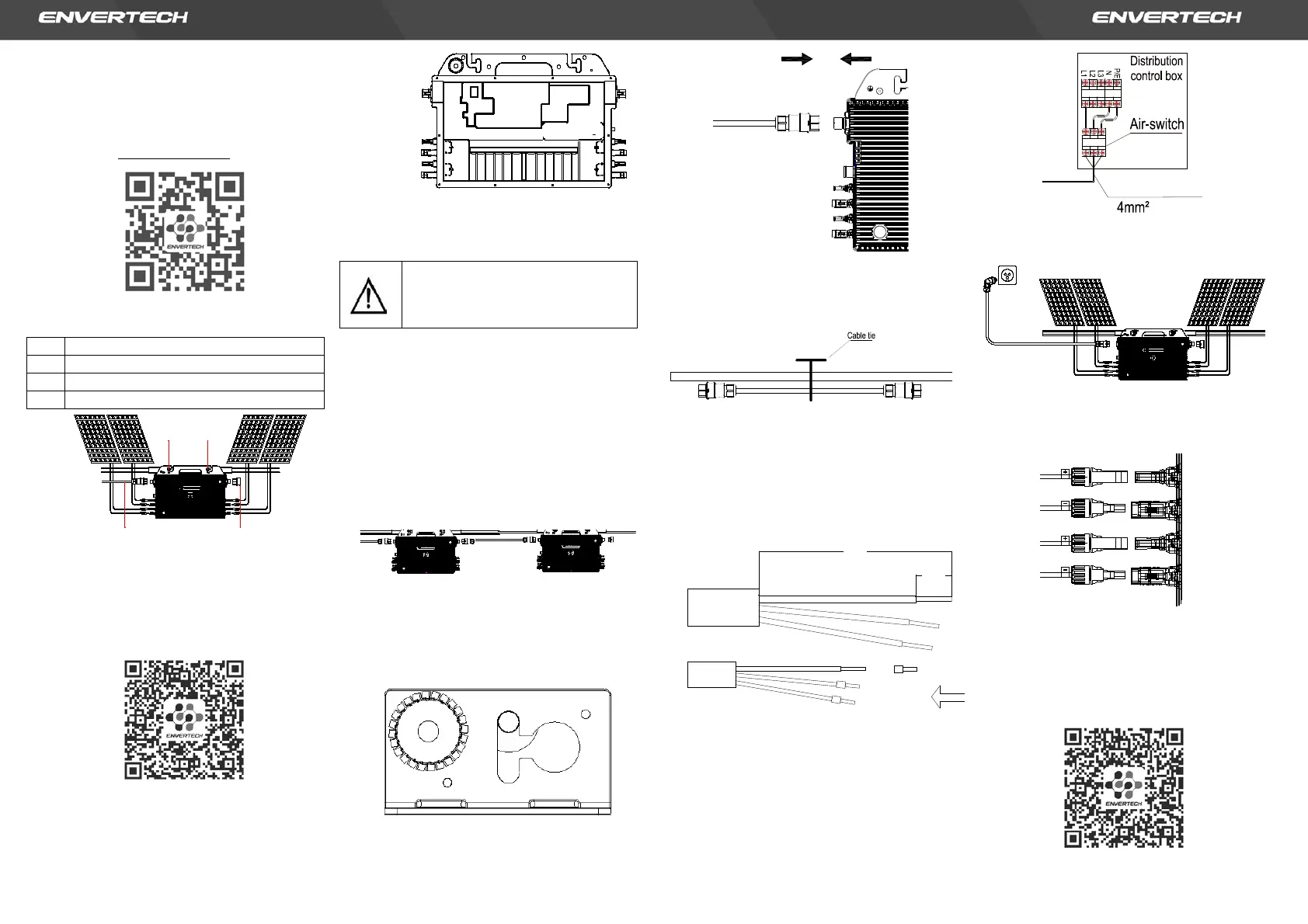
3. Installation Steps
Installation could only be implemented when the
system is disconnected from the grid, and the solar
panel has been covered or disconnected.
Step 1. Verify that grid voltage and PV panel
voltage are matching with microinverter
rating
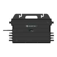
Step 2. Mount microinverters onto the rack
Mark out the estimated center of each PV mod-
ule on the rack to facilitate locating microinvert-
ers.
Mount all microinverters under modules to avoid
rain and sun, with the trademark facing down-
ward.
Note: Please make sure that there are less than 2
units of EVT2000 in each branch(1AWG).
Step 3. Ground the system
Microinverters and modules must be connected
to the grounding conductor in accordance with
national standards. Fix the screws to the mi-
croinverter installation hole. Make sure that the
grounding screw thread is pierced into the
bracket to get the best grounding effect.
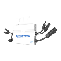
Step 4. Connect microinverter AC cables serially
Connect the AC connectors on both sides of the
microinverters in a hand-in-hand way.
Step 5. Fasten AC cables
Fasten AC cables and grounding cables to the
rack with cable ties.
Step 6. Connect to the grid
Option a. Connect to air switch
1) Remove the skin of the two ends of the ex-
tension cable by y=40mm and remove the
skin of internal wires by x=14mm. Set the
metal terminals onto the open parts and
clamp them to tighten the connection;
2) Connect the other side of the extension
cable to the air switch.
Option b. Put the open parts of the extension
cable into the plug and use the plug to con-
nect to the socket
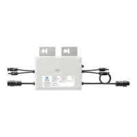
Step 7. Connect PV modules to microinverters
Mount the PV modules on top of the microin-
verters; Connect each PV module with the DC
input cables of the microinverter.
Step 8. Switch on the PV system
Ensure all connection is completed and then turn
on the air switch.
For the monitoring system (EnverBridge) installa-
tion please scan this QR code .
 Loading...