Do you have a question about the Envertech EVT2000 and is the answer not in the manual?
Provides essential preliminary instructions for safe installation and operation of the EVT2000 microinverter.
Outlines critical safety guidelines and precautions for using Envertech equipment to prevent injury or damage.
Explains how the Envertech microinverter maximizes energy production by using individual MPPT for each PV module.
Describes the EnverBridge as the monitoring device that reports real-time and historical performance data.
Highlights the inherent reliability of microinverter systems due to their distributed nature and single-point failure avoidance.
Details the ease of design and installation for PV systems using Envertech microinverters, simplifying the process.
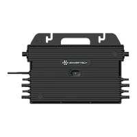
Introduces the EVT2000 microinverter and emphasizes installation according to manual instructions for reliability.
Lists key features of Envertech microinverters, including high efficiency, reliability, cost-effectiveness, and integrated protective functions.
Presents detailed technical specifications and electrical data for the EVT2000 microinverter.
Instructs users to check the carton for damage and verify the completeness of microinverter and accessories.
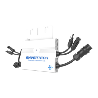
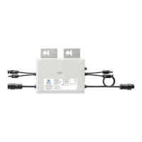
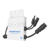
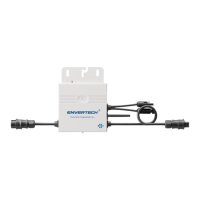
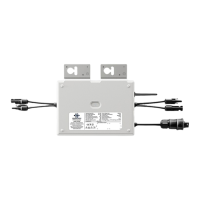
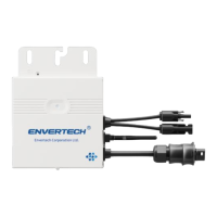
Provides a table listing the components of the EVT2000 microinverter and an illustration of its parts.
Directs users to the Envertech website or email for any further questions regarding accessories or installation.
Explains various safety symbols used on the inverter, indicating hazards like electrical voltage and hot surfaces.
Lists essential accessories for PV module installation, such as PV modules, AC extension cables, and AC end caps.
Provides guidance on selecting the appropriate AC Bus Cable type based on PV module orientation for installation.
Guides users through configuring the EVT400's WiFi using the Enverview app, including network selection and password entry.
Details the process of configuring the EVT400's WiFi settings using a web browser and computer.
Explains how to bind the microinverter (MI) to the Enverview app by logging in and entering the device's serial number.
Describes binding the microinverter via the EnverView app in local mode, connecting the EVT2000 directly.
Details the procedure for energizing the microinverter system, including turning on breakers and system startup.
Describes the normal operation of the EVT2000 microinverter, including LED indicators for startup and power production.
Explains the meaning of different LED light patterns for startup and post-startup status, indicating normal operation or failure.
Provides steps for qualified personnel to troubleshoot an inoperable microinverter, emphasizing safety precautions.
Illustrates the system diagram for a single-phase Envertech microinverter setup.
Shows the system diagram for a three-phase Envertech microinverter setup with EVB300.
The Envertech EVT2000 is an on-grid microinverter system designed to maximize energy production from photovoltaic (PV) arrays. This system utilizes world-top-class technology to convert direct current (DC) from PV modules into alternating current (AC) for utility grid connection. Each EVT2000 microinverter is individually connected to one PV module, featuring an individual Maximum Peak Power Point Tracker (MPPT) for each module. This unique configuration ensures that the maximum power available from each PV module is exported to the utility grid, regardless of the performance of other PV modules in the array or external factors like shading, soiling, orientation, or module mismatch. The result is optimized energy production from the PV system.
The Envertech microinverter system is characterized by its high efficiency, reliability, and cost-effectiveness. It operates with low DC input voltage and boasts a wide MPPT voltage range, which ensures high yield under various weather conditions. The high MPPT accuracy minimizes power loss during the conversion process. The system also integrates a comprehensive set of protective functions, including internal overvoltage/undervoltage protection, faulty grounding protection, and grid monitoring, as well as current monitoring in grounding DC current monitoring. The EVT2000 is adaptable to almost all PV modules, though users should verify compatibility between the microinverter and module parameters before installation.
A key component of the Envertech system is the EnverBridge monitoring device. Once installed and connected to a broadband router or modem, Envertech microinverters automatically report performance data to the EnverBridge server. The EnverBridge monitoring system provides both real-time and historical performance data, which can be viewed via a web browser on the EnverPortal (http://www.envertecportal.com) or through the EnverView app available for iOS and Android devices. This integrated solar system simplifies design, installation, and management while maximizing energy harvest and increasing system reliability.
The system's optimal reliability stems from the distributed nature of microinverter systems, which prevents a single point of failure in the PV system. Envertech Microinverters are designed for robust operation, capable of functioning at full power in ambient temperatures up to +65 °C (150 °F). The microinverter casing is built for outdoor installation and complies with the IP67 protection level, ensuring durability against environmental elements. For optimal reliability and warranty compliance, the EVT2000 microinverter must be installed strictly according to the instructions provided in the manual.
Installation of PV systems using Envertech microinverters is designed to be simple and straightforward. Users can combine PV modules of any type, orientation, and quantity without the need for cumbersome traditional inverters. Each microinverter can be quickly mounted on the PV rack, directly beneath its corresponding PV module. Low voltage DC wires connect the PV module directly to the co-located microinverter, thereby eliminating the risk of personnel exposure to dangerously high DC voltage.
Maintenance and troubleshooting for the EVT2000 system are outlined to ensure safe and effective operation. The manual emphasizes that only qualified personnel should install or replace Envertech microinverters and their associated cables and accessories. Users are warned against attempting to repair the microinverter themselves, as it contains no user-serviceable parts, and any tampering will void the warranty. In case of failure, users should contact Envertech customer service for replacement.
The microinverter's LED light provides status indications. During startup, the LED blinks red briefly, then green to indicate normal operation, approximately 10 seconds after DC power is applied. A continuous red blink after DC power is on signifies a startup failure. Post-startup, a flashing green LED indicates normal operation. A red light flashing every 2 or 3 seconds means the microinverter is waiting for sunlight or preparing to produce energy. A continuously flashing red light indicates abnormal operation, specifically that the microinverter does not detect the utility grid within the operable voltage/frequency range, preventing power production until the issue is resolved.
Troubleshooting an inoperable microinverter involves a systematic approach. Users should first ensure all AC and DC wiring is correct and undamaged. AC breakers must be on, and the connection to the utility grid verified for correct voltage within allowable ranges. AC voltage at all solar power circuit breakers of the load centers should be within specified ranges, and AC line voltage at the junction box for each AC branch circuit must meet local grid standards. The microinverter's connection to the grid should be confirmed by measuring voltage from AC line to line and line to neutral. Visual inspection for damage, such as rodent damage, and ensuring all circuit breakers are off are also crucial steps.
If problems persist, users are advised to disconnect and reconnect the PV modules' DC connectors with the microinverters. The LED status should blink green, indicating normal startup. An ammeter clamp can be used to measure the microinverter's current from one conducting wire of the DC cables; this should be under 1 Amp if AC is disconnected. The DC connection between the microinverter and the PV module should be checked for tightness or damage. Finally, verifying grid frequency with the utility company is recommended.
For situations requiring microinverter replacement, specific disconnection procedures must be followed to ensure safety and prevent operation during the process. This includes turning off the AC branch circuit breaker, pulling the AC connectors in opposite directions, covering the PV module with an opaque material before disconnecting DC connectors, loosening the grounding screw, and then removing the microinverter from the PV frame.
The manual also addresses recycling and disposal. To comply with regulations for electrical and electronic waste management, equipment that has reached its lifetime must be collected separately by qualified units or individuals for disposal. Users are instructed to return old equipment to their dealer for recycling or send it to an approved recycling unit in their area.
| Model | EVT2000 |
|---|---|
| Rated Output Power | 2000W |
| Output Voltage | 230V |
| Nominal Output Current | 8.7A |
| Output Frequency | 50/60Hz |
| Power Factor | >0.99 |
| Cooling | Natural Convection |