11
Temperature sensor
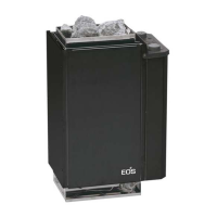
Installation
Remove the sauna heating unit from the packaging
and pull off the protective foil on the stainless steel and
exterior housing components.
To install the unit, the rear wall is first removed from the
unit by pulling it downward while the unit is tilted or
lying on its side.
Mount the rear wall panel to the cabin wall using the
enclosed 4 tension plate screws in accordance with
the dimensions shown in Fig. 2.
Caution! The cams of the mounting holes must not
be set in a groove, as this will create a space between
the rear wall of the heater and the cabin wall.
Next, set the heater unit onto the rear wall from above.
Ensure that the vertical angular segments of the side
walls are flush with the cabin wall (Fig. 3 and 4).
Drill a hole measuring approx. 12 mm in diameter near
the fresh-air inlet and push the power cable through this
hole to the cabin exterior. The power cable should be
connected to the power supply in a distributor box
suitable for use in moist environments.
20 x 4
22 cm
Holes always positioned
in the center of a
profile panel
Fig. 2
Fig. 3
Fig. 5
Fresh-air inlet
Installation of the sensor mounting bracket
and temperature sensor
The sensor mounting bracket is mounted (using the
two wood screws provided) on the cabin wall above
the heater as shown in Fig. 6, approx. 25 cm below the
cabin ceiling.
The capillary tubes are mounted to the cabin wall
using the provided brackets. Please ensure that the
capillary tubes are not bent at a sharp angle.
The excess length of capillary tube should be rolled up
behind the heater and must not be pushed back into
the connection box under any circumstances.
Fig. 6
Fig. 4
 Loading...