57
REV. 07/2016
OPERATING SYSTEM
6
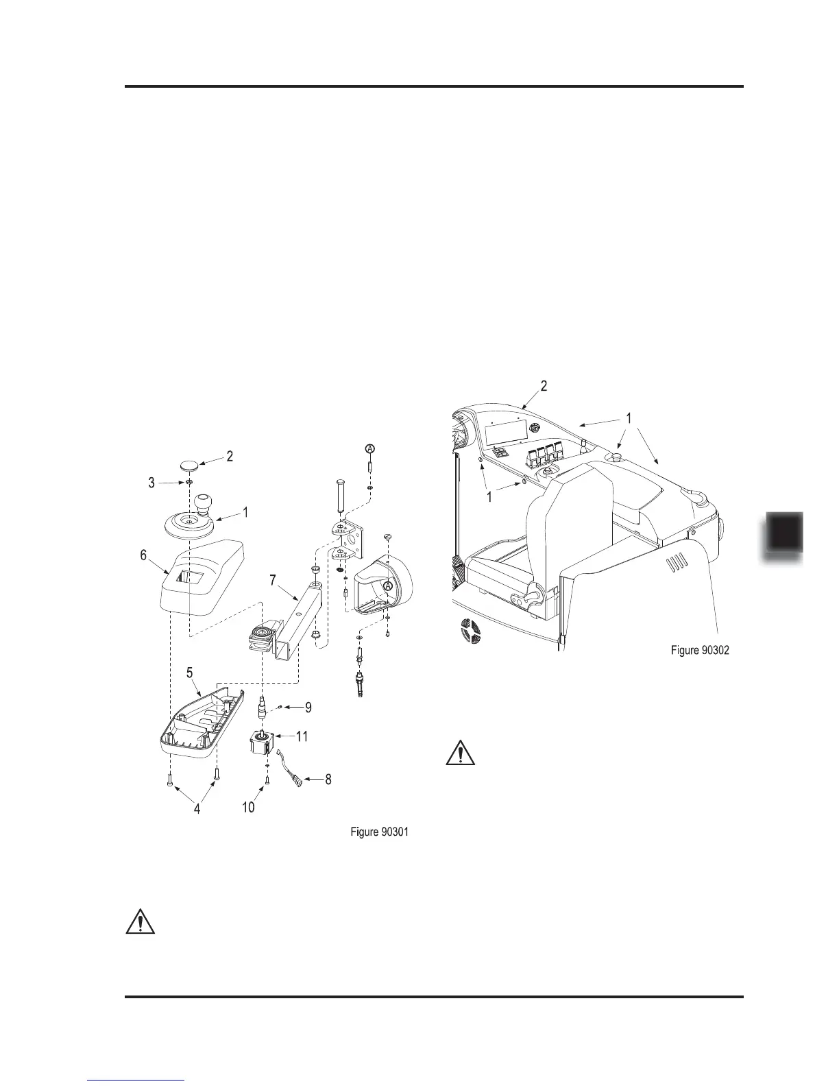
6.1 Control Lever
Removal
-
-
-
-
-
Open the plastic cover (2) on the steering
wheel (1);
Unscrew the nut (3) and remove the steering
wheel (1);
Unscrew the screw (4), remove the top cover
(6) and bottom cover (5) from operating
handle (7);
Disconnect the stepper motor wiring harness
(8);
Unscrew the fastening screw (9), unscrew
the four screws (10) and remove the stepper
motor (11).
Control lever is mounted on operating handle
(7,Figure 90301).
-
Install according to the reverse order of rem-
oval;
When removing or installing, please pay attent-
ion to protect the cables from being damaged.
CAUTION
6.2 Control Panel
Removal
-
-
-
Unscrew the 10 screws (1,Figure 90302),
raise the front cover (2) up from the chassis;
Disconnect the components on the front
cover from main harness;
Replace the components that need to be
replaced: rocker switch (warning light and
headlights), travel switch, key switch, control
switch (configuration of CQD16/20 (N) RVF
model), emergency stop switch, horn button
or instrument.
Installation
-
Install according to the reverse order of rem-
oval;
When removing or installing, please pay attent-
ion to protect the cables from being damaged.
CAUTION
Installation
 Loading...