EasyManua.ls Logo

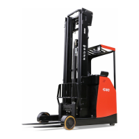
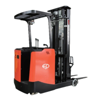
EP Equipment CQD20RVF User Manual

Default Icon
251 pages
To Next Page IconTo Next Page
Page #1 background imageLoading...
Page #1 background image
Service Manual
Electric Reach Truck
CQD16NRVF/NRV
CQD16/20RVF/RV

Table of Contents

Questions and Answers:

EP Equipment CQD20RVF Specifications

General IconGeneral
BrandEP Equipment
ModelCQD20RVF
CategoryTrucks
LanguageEnglish

Summary

SAFETY WARNING

1. INFORMATION & SPECIFICATIONS

1.1 After-sales Service Platform

Outlines claims and maintenance service processes for customer support.

2. MAINTENANCE

2.1 Overview

Emphasizes the importance of regular maintenance and qualified personnel.

2.2 Maintenance

Details procedures for cleaning and inspecting the equipment.

2.2.2 Inspection

Outlines inspection intervals and procedures under various operating conditions.

2.2.3 Lubrication

Explains lubrication procedures, types of lubricants, and application points.

3. STRUCTURE & FUNCTIONS

3.1 Structure & Functions

Details the various structural components and their functions within the truck.

4. CHASSIS SYSTEM

5. DRIVE SYSTEM

5.2 Electromagnetic Brakes

Details the removal, installation, adjustment, and testing of electromagnetic brakes.

5.3 Drive Motor

Covers the removal, installation, testing, and troubleshooting of the drive motor.

5.6 Steering Motor

Covers the removal, installation, testing, and troubleshooting of the steering motor.

7. HYDRAULIC SYSTEM

7.1 Overview

Provides an overview of the hydraulic system, its pressure, and key components.

8. ELECTRICAL SYSTEM

8.1 Controller

Details controller functions, removal, and installation.

8.1.2 Controller Interface Function

Describes the interface functions for the Traction Controller (AC2).

Pump Controller (AC2-PUMP)

Explains the interface functions for the Pump Controller.

Instrument (SICOS)

Details the interface functions for the Instrument (SICOS).

Solenoid Valve Controller (MHYRIO FLASH) RVF/NRVF

Explains the interface functions for the Solenoid Valve Controller.

8.2 Fuse

Details the vehicle's fuses, their functions, status, and locations.

8.3 Main Contactor

Covers the main contactor's operation, removal, installation, and faults.

8.12 Instrument

Describes the instrument panel layout and operation schematics.

Traction / Pump Controller (AC2)

Lists parameters and remarks for the Traction/Pump Controller in TESTER Menu.

Steering Controller (EPS-AC0)

Lists parameters and remarks for the Steering Controller in TESTER Menu.

8.14 Controller Error Message

Lists error messages, possible causes, and fault eliminations for the Traction/Pump Controller.

8.14.2 Steering Controller (EPS-ACO)

Lists error messages, possible causes, and fault eliminations for the Steering Controller.

8.14.3 SICOS Controller

Lists error messages and fault eliminations for the SICOS Controller.

8.14.4 Solenoid Valve Controller

Lists error messages and fault eliminations for the Solenoid Valve Controller.

8.15 Electrical Schematic Diagrams RVF/NRVF

Presents electrical schematic diagrams for RVF/NRVF models, broken into parts.

8.16 Electrical Schematic Diagrams RV/NRV

Presents electrical schematic diagrams for RV/NRV models, broken into parts.

9. TROUBLESHOOTING

9.1 Preparation Before Troubleshooting

Outlines essential preparation steps before starting troubleshooting.

9.1.1 Check the Voltage of Battery

Details procedures for checking battery voltage and identifying issues.

9.2 Troubleshooting Solutions of Common Faults

Provides common fault symptoms, causes, and troubleshooting measures.

A SERVICE MANUAL - MAST

A1 Two-stage Mast

Details the removal and installation of the two-stage mast.

A1-4 Lift Cylinder

Details the removal and installation of lift cylinders for the mast.

A1-5 Tilt Cylinde

Covers the removal and maintenance of tilt cylinders.

A1-6 Built-in Side Shifter

Details the removal, installation, and maintenance of the built-in side shifter.

A2 Three-stage Mast (Lifting Height ≤ 7.5 m)

Explains removal and installation for a three-stage mast up to 7.5m.

A2-4 Lift Cylinder

Details the removal and installation of lift cylinders for the three-stage mast.

B SERVICE MANUAL - BATTERY

B1-5 Troubleshooting

Provides battery fault analysis, causes, and handling methods.

Related product manuals