Do you have a question about the Epiroc YT29A and is the answer not in the manual?
Details critical safety guidelines and signal words for machine use.
Outlines operator qualifications and mandatory protective equipment.
Dangers from impairment, installation, and general operation.
Risks from dust, fumes, and vibration exposure during use.
Procedures, warnings, and modification risks during maintenance.
Recommendations for safe machine storage when not in use.
Describes the intended uses and suitability of the rock drills.
Details the technical data for different rock drill models.
Explains the meaning of labels and elements on the machine's data plate.
Initial setup steps and pre-operation checks for the rock drill.
Operation of levers, triggers, and feed controls for machine management.
Step-by-step guides for core operational sequences.
Essential checks performed at various operational intervals.
Guidance on the importance of using genuine replacement parts.
Cold weather measures and guidelines for environmentally sound waste disposal.
Information on noise/vibration exposure and related risks.
Detailed technical data for various pusher leg models.
Statement of compliance with EC machinery directives.
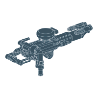
Visual diagram showing the assembly of YT29A parts.
Visual diagram showing the assembly of YT29AE parts.
Visual diagram showing the assembly of YT29AE(T) parts.
Visual diagram showing the assembly of 7655D parts.
The Secoroc YT29A, T29AE, YT29AE(T), and 7655D pusher leg rock drills are robust and versatile tools designed for a wide range of drilling applications, particularly in mining, quarrying, and construction. These drills are engineered to deliver high performance and productivity, making them suitable for both surface and underground operations. Their primary function is to create boreholes in rock formations, facilitating tasks such as blasting, bolting, and exploration. The pusher leg mechanism provides essential feed force, enhancing drilling efficiency and reducing operator fatigue.
At its core, the rock drill operates on a pneumatic principle, utilizing compressed air to power a reciprocating piston that strikes the shank of a drill steel. This percussive action, combined with rotation, effectively breaks and removes rock material. The pusher leg, a key component, extends and retracts to provide the necessary thrust to advance the drill steel into the rock. This controlled feed ensures optimal penetration rates and minimizes the risk of the drill getting stuck. The drills are designed for both wet and dry drilling, with provisions for water flushing to clear cuttings and cool the drill bit, or air flushing for dry applications.
The internal mechanism involves a complex interplay of valves and channels that direct compressed air to drive the piston and rotate the drill steel. The rotation mechanism, typically a rifle bar, converts the linear motion of the piston into rotational movement, ensuring continuous cutting action. The control system allows the operator to manage both the percussive force and the rotation speed, adapting to different rock types and drilling conditions. The trigger mechanism initiates and stops the drilling process, while a separate control regulates the pusher leg feed force.
These rock drills are designed with operator safety and efficiency in mind. Before starting any drilling operation, it is crucial to perform a thorough pre-start check, including inspecting air hoses, connections, and the drill steel itself. Proper fitting of the working tool is essential to prevent damage and ensure effective drilling. The operator must ensure that all connections are secure and that the air supply is clean and adequately lubricated.
During operation, the operator holds the drill firmly, maintaining a stable stance to control the tool. The pusher leg is engaged to provide the necessary feed force, and the drilling process begins. The operator continuously monitors the drilling action, adjusting the feed force and rotation speed as needed. Stopping the rock drill involves disengaging the percussive and rotation mechanisms, followed by retracting the pusher leg and removing the drill steel from the borehole.
For repositioning the pusher leg or moving the drill to a new hole, the operator must ensure the drill is safely disengaged from the rock. When drilling is completed, proper procedures for shutting down the machine, cleaning, and storing the tool must be followed. The drills are designed to be user-friendly, but proper training and adherence to safety instructions are paramount to prevent accidents and ensure optimal performance. The controls are intuitively placed, allowing for easy manipulation of the throttle, trigger, and pusher leg.
The versatility of these drills extends to various drilling angles and positions, making them adaptable to different geological formations and operational requirements. The robust construction ensures durability in harsh working environments, while ergonomic design considerations aim to reduce operator strain during prolonged use. The ability to switch between wet and dry drilling modes further enhances their adaptability, allowing for efficient operation in diverse conditions where dust suppression or cutting removal methods may vary.
Regular and systematic maintenance is critical to ensure the longevity, reliability, and optimal performance of the Secoroc rock drills. The maintenance schedule is divided into daily, weekly, monthly, and periodic checks, each addressing specific components and functions.
Daily maintenance includes checking for loose connections, air leaks, and damage to hoses and the drill steel. The lubrication system, which typically involves an in-line oiler, must be checked daily to ensure an adequate supply of lubricant. Proper lubrication is vital for reducing wear on internal components and preventing corrosion. After each shift, the drill should be cleaned thoroughly to remove rock dust and debris, which can otherwise accumulate and cause blockages or premature wear.
Weekly maintenance involves more detailed inspections, such as checking the chuck bushing for wear, inspecting the rifle bar and rotation mechanism, and verifying the condition of all seals and O-rings. Any worn or damaged parts should be replaced immediately using genuine spare parts to maintain the drill's integrity and performance.
Monthly maintenance, or after a specified number of operating hours, requires a more comprehensive overhaul. This includes disassembling key components, cleaning them, inspecting for wear, and replacing any parts that show signs of significant deterioration. Special attention is given to the piston, cylinder, valve chest, and pusher leg assembly. The lubrication system should be thoroughly checked, and the oiler refilled with the recommended lubricant.
Periodic maintenance, typically after several hundred hours of operation, involves a complete strip-down and inspection of the entire drill. This allows for a detailed assessment of all internal components, including bearings, gears, and wear parts. Any components nearing the end of their service life should be replaced. This comprehensive approach ensures that the drill operates at peak efficiency and minimizes the risk of unexpected breakdowns.
Scrapping and waste disposal procedures are also outlined, emphasizing environmentally responsible practices for handling worn-out parts and lubricants. Measures to prevent freezing are important in cold climates, requiring proper storage and, if necessary, the use of anti-freeze solutions in the water flushing system. Adherence to CE Declaration of Conformity ensures that the drills meet European safety and environmental standards.
Troubleshooting guidelines are provided to help operators identify and resolve common issues, such as decreased penetration rate, insufficient feed force, poor rotation, and uneven running. These guidelines offer practical solutions, from checking air supply and lubrication to inspecting specific components for wear or damage. Regular training for maintenance personnel is essential to ensure they are proficient in performing these tasks, further contributing to the drill's operational efficiency and safety.
| Category | Drill |
|---|---|
| Weight | 29 kg |
| Air Consumption | 0.8 m³/min |
| Shank Size | 22 x 108 mm |
| Recommended Drill Steel | R32 |