6
Step 4: Drill Holes
Remove the controller and drill four sizeable holes in the marked locations
Step 5: Secure Controller
Place the controller on the surface and align the mounting holes with the drilled
holes in step 4 Secure the controller in place using the mounting screws
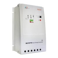
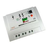
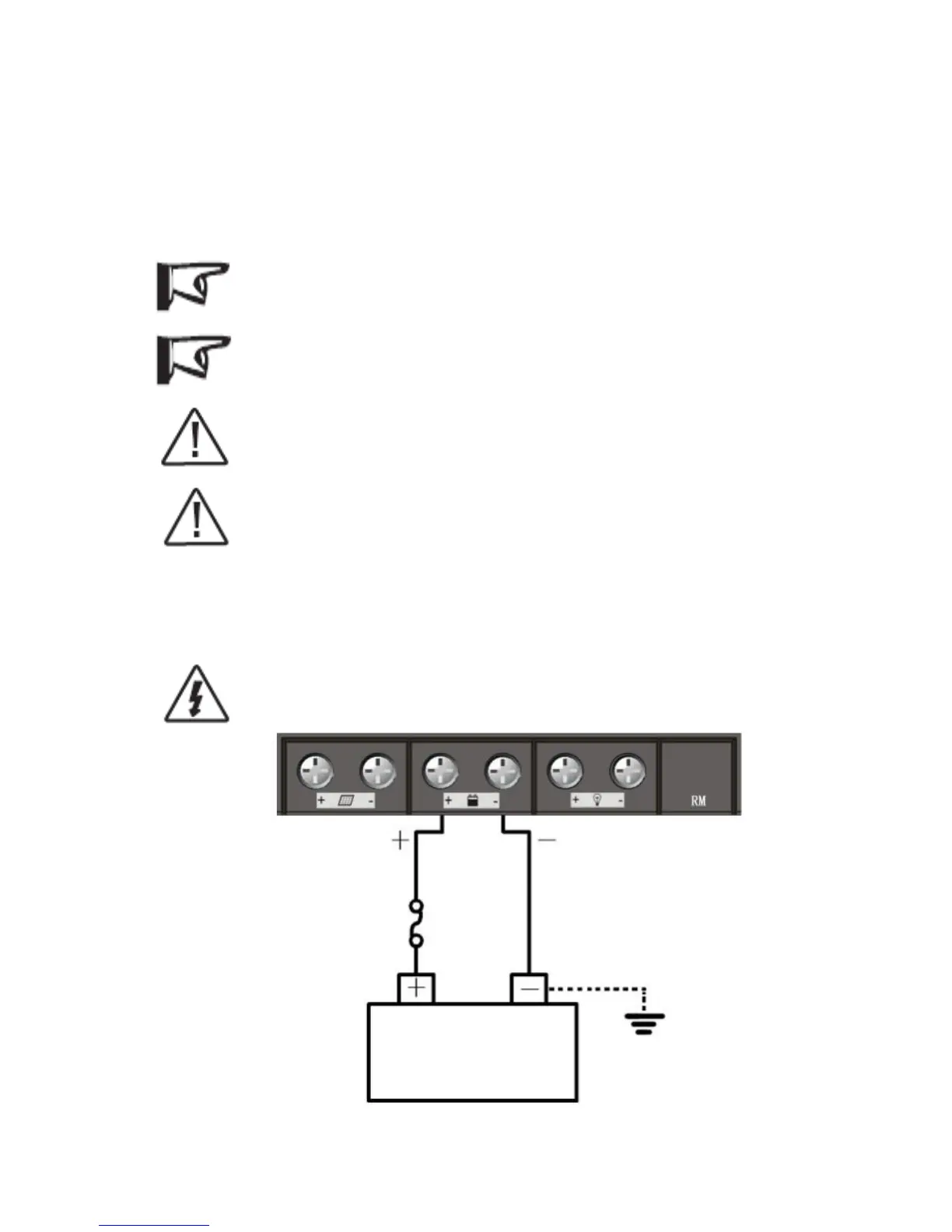
3.3 Wiring
NOTE: A recommended connection order has been provided for maximum
safety during installation.
NOTE: The Tracer is a negative ground controller. Any negative connection of
solar module, battery or load can be earth grounded as required. Grounding is
recommended.
CAUTION: Don’t connect the loads with surge power exceeding the ratings of
the controller.
CAUTION: For mobile applications, be sure to secure all wiring. Use cable
clamps to prevent cables from swaying when the vehicle is in motion. Unsecured
cables create loose and resistive connections which may lead to excessive heating
and/or fire.
Step 1: Battery Wiring
WARNING: Risk of explosion or fire! Never short circuit battery positive (+)
and negative (-) or cables
Figure 3-1 Battery wiring
 Loading...