EasyManua.ls Logo

Epson Computer User Manual

Epson Computer
10 pages
To Next Page IconTo Next Page
To Previous Page IconTo Previous Page
Page #5 background image
EPSON Endeavor L
-
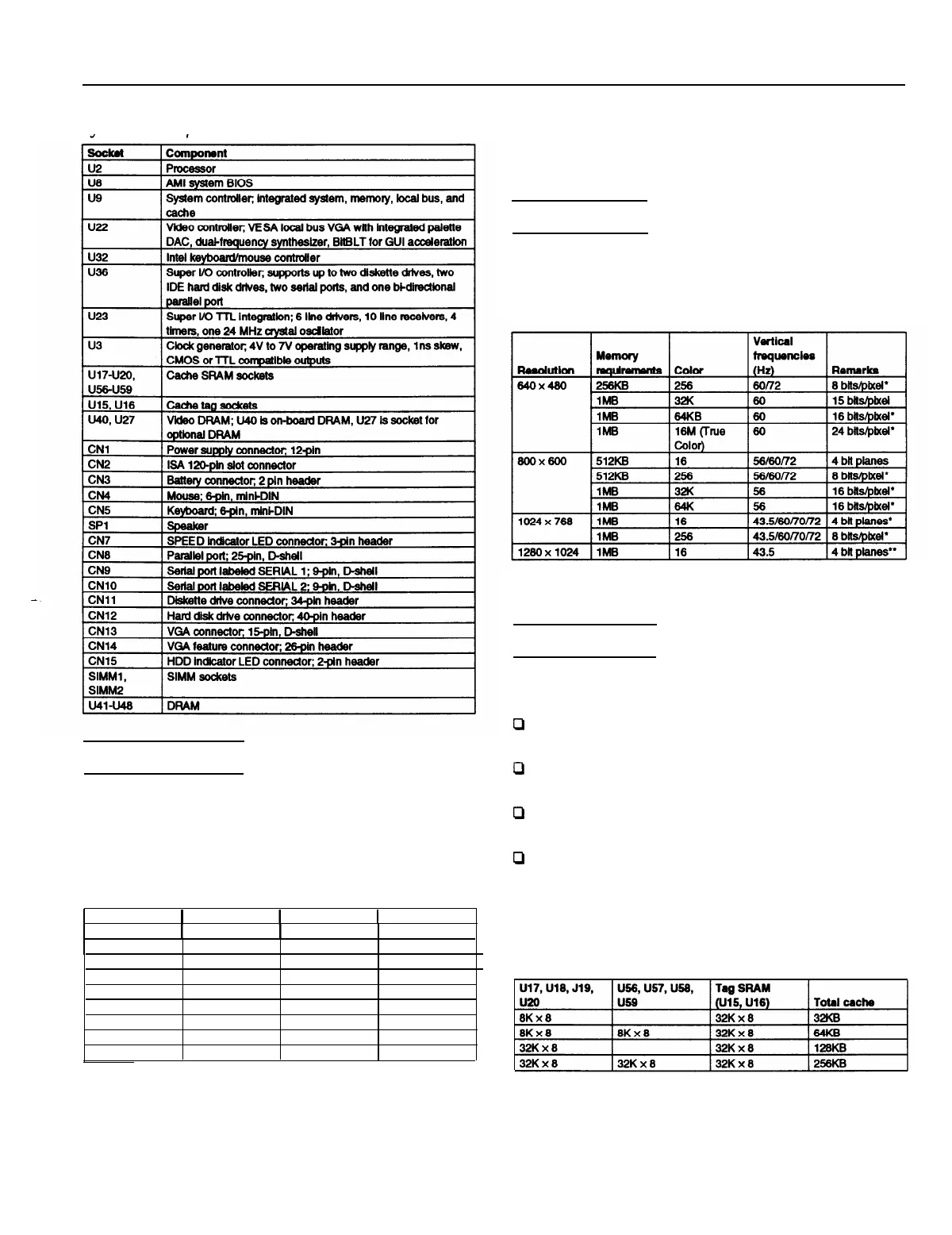
System board components and connectors
SIMM Installation
Your computer comes with 4MB of memory on the system
board. You can increase the memory up to 36MB by installing
1MB, 4MB, and 16MB SIMMs in the computer’s two SIMM
sockets. The following table shows the possible SIMM
configurations. You can install SIMMs in either SIMM socket.
SIMM
configuration
On-board
1
SIMM1
1
SIMM2
1
Total
memory
4MB
1
None
1
None
4MB*
4MB
1MB
4MB
1MB
4MB
4MB
4MB
4MB
4MB
16MB
4MB
16MB
4MB
16MB
4MB
16MB
None
1MB
None
4MB
None
1MB
4MB
16MB
5MB
6MB
8MB
12MB
20MB
21MB
24MB
36MB
l
Standard memory on the system board
Use only 32-bit, 72-pin, fast-page mode SIMMs that operate
at an access speed of 70ns. If 32-bit SIMMs are unavailable,
you can use 36-bit SIMMs instead.
Video Memory
This system comes with 512KB or 1MB of video memory. You
can increase the video memory to 1MB by installing a video
DRAM, 40-pin, 256KB x X-bit, SOJ chip.
Video resolutions and colors
l
Non-interlaced and interlaced
** Interlaced
External Cache
EPSON Authorized Servicers can install 32KB, 64KB, 128KB,
or 256KB of external cache on this system.
0
To install 32KB or 64KB of external cache, use SRAM,
28-pin, 8 x 8, 20ns DIP chips
P
To install 128KB or 256KB of external cache, use SRAM,
28-pin, 32 x 8, 20ns DIP chips
0
For all configurations of external cache, use two 28-pin,
32 x 8, 15ns tag chips
0
If you install external cache, make sure you set jumpers J5,
J6, J7, J8, and J9 as described on page 3.
For the cache memory to work properly, you must install
chips in the following configuration (each bank contains four
cache memory sockets).
Cache memory configurations
3/94
EPSON Endeavor L - 5
Question and Answer IconNeed help?

Do you have a question about the Epson Computer and is the answer not in the manual?

Epson Computer Specifications

General IconGeneral
BrandEpson
ModelComputer
CategoryComputer Hardware
LanguageEnglish

Summary

EPSON Endeavor L System Overview

Memory System Details

Details on system memory, including RAM standard, expansion, and SIMM requirements.

ROM and BIOS Information

Information on system and video BIOS and SETUP code located in EPROM.

Video RAM Configuration

Details on standard and expandable Video RAM (DRAM) on the system board.

Shadow RAM Functionality

Explains the support for shadowing system and video BIOS ROM into RAM.

Cache Memory Specifications

Information on internal and external cache support and chip requirements.

Math Coprocessor Support

Details on installing an 80487SX processor or built-in coprocessors.

Clock and Calendar Feature

Description of the real-time clock, calendar, and CMOS RAM with battery backup.

Computer Specifications

32-bit CPU Details

Information on the Intel 486SX, DX, or DX2 processor and upgrade options.

Energy Star Compliance

Details on low power consumption and Energy Star compliance.

System Speed Settings

How to select between fast and slow processor speeds and default settings.

Video Controller

Cirrus Logic CD5428 high speed VGA local bus controller with True Color.

Diskette Controller

Controller on main system board supporting up to two diskette drives or one tape drive.

Hard Disk Controller

Interface supporting up to two IDE hard disk drives with built-in controller.

Monitor Interface

Local bus SVGA interface for monitors with a 15-pin connector.

System Connectivity and Ports

SVGA Feature Connector

SVGA pass-through interface built into the main system board.

Parallel Port

One standard 8-bit parallel interface, selectable I/O address, 25-pin connector.

Serial Ports

Two RS-232C, programmable, asynchronous interfaces with 9-pin connectors.

Keyboard and Mouse Ports

PS/2 compatible keyboard and mouse interfaces with 6-pin mini DIN connectors.

Option Slots Overview

Four 16-bit (or 8-bit) I/O expansion slots, ISA compatible, 8.33 MHz bus speed.

Internal Speaker

Internal, piezo-electric speaker connected to the main board.

Mass Storage Options

Diskette Drive Options

Details on 3.5-inch and 5.25-inch diskette drives and their storage capacities.

Hard Disk Drive Installation

Information on 3.5-inch form factor hard disk drives and mounting bays.

Other Storage Devices

Support for half-height tape drives, CD-ROM drives, or optical drives.

System Configuration and Security

System Security Features

Password protection for system boot and keyboard unlock, definable hot keys.

Virus Protection

Write protection feature for the boot sector of the hard disk drive.

SETUP Program Access

How to access the SETUP program stored in ROM via the Delete key.

Processor Upgrades and Compatibility

Microprocessor Upgrade Options

Details on replacing the existing processor with faster or compatible models.

Hard Disk Drive Types

Table listing supported hard disk drive types and their parameters for SETUP.

Drive Option Information

Specific drive option parameters for 1-inch IDE drives from various manufacturers.

Hardware Interrupts and DMA

Hardware Interrupt Assignments

List of IRQ numbers and their assigned functions and devices.

System Memory Map Overview

Diagram showing the memory map, including ROM, extended, and conventional memory.

DMA Assignments

List of DMA levels and the devices assigned to them.

System I/O Address Map and Pin Assignments

System I/O Address Map

Table detailing hex addresses and assigned system devices and controllers.

Parallel Port Pin Assignments

Pinout details for the parallel port connector (CN8).

Serial Port Pin Assignments

Pinout details for the serial port connectors (CN9, CN10).

Keyboard Connector Pin Assignments

Pinout details for the keyboard connector (CN5).

Mouse Connector Pin Assignments

Pinout details for the mouse connector (CN4).

VGA Port Connector Pin Assignments

Pinout details for the VGA port connector (CN13).

VGA Feature Connector Pin Assignments

Pinout details for the VGA feature connector (CN14).

Connector Pinouts and Booting Sequence

Power Supply Connector Pin Assignments

Pinout details for the power supply connector (CN1).

Diskette Drive Connector Pin Assignments

Pinout details for the diskette drive connector (CN11).

Hard Disk Drive Connector Pin Assignments

Pinout details for the hard disk drive connector (CN12).

Option Card Riser Board Connector Pin Assignments

Pinout details for the option card riser board connector (CN2).

Option Slot Connector Pin Assignments

Pinout details for the option slot connectors.

Speaker Connector Pin Assignments

Pinout details for the speaker connector (SP1).

Battery Connector Pin Assignments

Pinout details for the battery connector (CN3).

SIMM Socket Pin Assignments

Pinout details for SIMM sockets (SIMM1, SIMM2).

Booting Sequence Configuration

Instructions for setting the booting sequence in SETUP if the computer fails to boot.

Password Management

Instructions for setting and disabling the system password and hot key.

Installation and Support Information

Installing Diskette Drives

Guidance on correctly selecting the drive type in the SETUP program for diskette drives.

Installing Hard Disk Drives

Instructions for selecting hard disk drive types and using user-defined types.

Software Installation Tips

Recommendations for installing copy-protected software at high or low speeds.

Information Reference List

List of available technical information bulletins and related documentation.

Related product manuals