Do you have a question about the Epson Stylus Photo P50 and is the answer not in the manual?
| Print technology | Inkjet |
|---|---|
| Maximum resolution | 5760 x 1440 DPI |
| Print head nozzles | 90 |
| A6 Card | Yes |
| Connectivity technology | Wired |
| Compatible ink types, supplies | Epson Claria Photographic Ink |
| Print speed (black, normal quality, A4/US Letter) | 37 ppm |
| Print speed (color, normal quality, A4/US Letter) | 38 ppm |
| Envelopes sizes | C6, DL |
| Maximum print size | A4 (210 x 297 mm) |
| Standard media sizes | A4 \\r Letter \\r Legal \\r 20x25 cm \\r 13x18 cm \\r 10x15 cm \\r 9x13 cm \\r 13x20 cm \\r 102x181 mm \\r A6 \\r A5 \\r B5 \\r Half Letter \\r Envelopes: No.10, DL, C6, User Defined |
| Non-ISO print media sizes | Legal (media size), Letter (media size) |
| Package depth | 520 mm |
| Package width | 352 mm |
| Package height | 245 mm |
| Package weight | 6950 g |
| Bundled software | Epson Easy Photo Print\\r Epson Print CD\\r Epson Web-To-Page |
| Quantity per pack | 1 pc(s) |
| Card reader integrated | - |
| Sound pressure level (printing) | 34.7 dB |
| Built-in display | No |
| Country of origin | Philippines |
| Market positioning | Home & office |
| USB 1.1 ports quantity | 1 |
| AC input voltage | 220 - 240 V |
| Pallet width | 800 mm |
| Pallet height | 2110 mm |
| Pallet length | 1200 mm |
| Pallet width (UK) | 1000 mm |
| Quantity per pallet | 32 pc(s) |
| Quantity per pallet (UK) | 40 pc(s) |
| Quantity per pallet layer | 4 pc(s) |
| Quantity per pallet layer (UK) | 5 pc(s) |
| Depth | 289 mm |
|---|---|
| Width | 450 mm |
| Height | 187 mm |
Details the six chapters and appendix included in the service manual.
Explains the various symbols used to convey information or warnings.
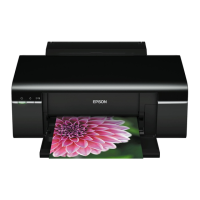
Provides a general overview and key features of the printers.
Details specifications related to printing, including resolution and paper handling.
Describes the printer's interface specifications, primarily USB.
Covers electrical, environmental, durability, and safety specifications.
Explains the functions of the printer's operational buttons and status LEDs.
Introduces the printer mechanism and main control boards.
Explains systems for improving print quality and feed accuracy.
Details the step-by-step sequence when the printer is powered on.
Describes the different methods for initializing the printer.
Guide to troubleshooting printer problems using driver messages, LED status, and symptoms.
Explains how the printer indicates errors or warnings via LEDs and driver messages.
Provides procedures for troubleshooting specific error messages indicated by LEDs or software.
Offers solutions for common printer issues not indicated by specific error messages.
Introduces the procedures for disassembling main printer components.
Lists critical warnings and cautions to follow during disassembly and assembly.
Specifies the tools required for disassembly and assembly to avoid damage.
Details the types of screws used in the printer for correct reassembly.
Provides instructions on how to create a special tool for CSIC board removal.
A checklist to confirm all servicing tasks are completed before returning the printer.
Lists essential steps to perform before starting the disassembly process.
Explains the orientation terms used in disassembly and reassembly procedures.
Provides instructions on how to unlock the printer carriage for disassembly.
Highlights differences in disassembly/reassembly for specific printer models.
A flowchart illustrating the step-by-step disassembly process for the printer.
Details the removal procedures for external printer components.
Provides instructions for removing main control boards like the Main Board and Panel Board.
Guides through the disassembly of the printer's internal mechanical components.
Specific disassembly procedures for Artisan 50/Stylus Photo T50/T59/T60/P50 models.
Lists and describes necessary adjustments after part replacement.
Table indicating which adjustments are needed based on replaced parts.
Instructions on how to use the adjustment program and interpret patterns.
Procedures for adjusting BRS and PFP systems for print quality.
Information on maintaining the printer in optimal condition.
Procedures for cleaning exterior parts, interior, and the LD Roller.
Actions to clear errors like abnormal prints or maintenance requests.
Details on the type and amount of grease for lubricating printer parts.
Indicates where to find exploded diagrams and parts lists (SPI).