EPSON Stylus CX7300/CX7400/DX7400/NX200/TX200 series/SX200 series/Stylus CX8300/CX8400/DX8400/NX400/TX400 series/SX400 series Revision C
DISASSEMBLY/ASSEMBLY Removing the Circuit Boards 106
Confidential
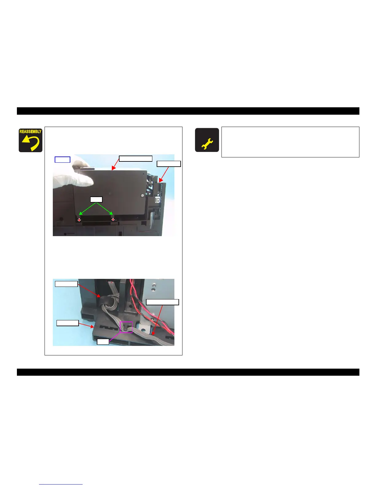
When installing the Power Supply Unit, make sure to check the
following points.
Insert the tabs (x2) of the Power Supply Unit into the holes on
the Base Frame.
Figure 4-28. Installing the Power Supply Unit
Tighten the screws in the order given in Figure 4-27.
Secure the Power Unit Cable with the hook of the Base Frame
as shown in the figure below.
Put the ferrite core of the Power Supply Unit cable into the
cutout of the Base Frame.
Figure 4-29. Routing the Power Unit Cable
 Loading...