EPSON Stylus CX7300/CX7400/DX7400/NX200/TX200 series/SX200 series/Stylus CX8300/CX8400/DX8400/NX400/TX400 series/SX400 series Revision C
DISASSEMBLY/ASSEMBLY Removing the Circuit Boards 105
Confidential
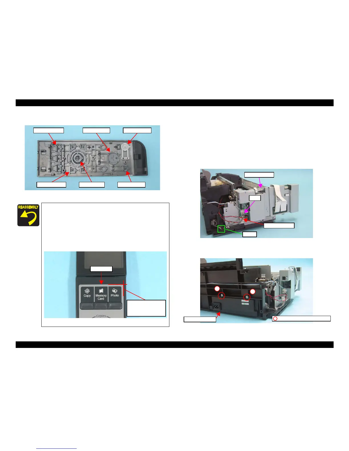
9. Remove each switch button from the Panel Cover.
Figure 4-24. Removing the Switch button
4.4.3 Power Supply Unit
Parts/Components need to be removed in advance
Document Cover/ASF Cover/Scanner Unit/Panel Unit/Upper Housing/Card Slot
Cover/Lower Housing
Removal procedure
1. Disconnect the connector of the Power Supply Unit (CN1) on the Main
Board.
2. Release the Power Unit Cable from the hook of the Base Frame.
Figure 4-26. Removing the Power Supply Unit (1)
3. Remove the screws (x2) that secure the Power Supply Unit.
4. Lift the Base Frame a little, and remove the Power Supply Unit.
Figure 4-27. Removing the Power Supply Unit (2)
When installing the Panel Board, match the positioning holes
of the Panel Board with their positioning pins of the Panel
Housing as shown in
Figure 4-23.
Tighten the screws in the order given in Figure 4-23.
The Panel Sheet is not included in the ASP unit of the Panel
Unit. When replacing the Panel Unit, order the Panel Sheet
separately and attach it on the specified place as shown in the
figure below.
Figure 4-25. Panel Sheet Position
 Loading...