Manual Override Procedures
If electrical power is lost to the leveling or slide-out system, your system has been equipped with a manual override option.
A coach may come equipped with either a Bi-Rotational or a Uni-Directional Pump Assembly. Please refer to the diagrams
in the following section to identify which type of pump assembly is installed on the vehicle.
Bi-Rotational
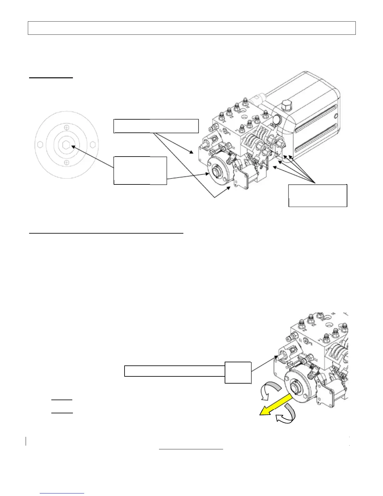
This pump is identified by TWO (2) MOTOR SOLENOIDS and
TWO (2) POWER POSTS on the motor.
Two (2) motor solenoids
Motor End 1/4 “
(6mm) or 7/16”
(11mm) Hex
Cartridge Valves
(4) shown
The hydraulic pump assembly is equipped with a 1/4 “ Allen Drive Socket (6mm) or 7/16” (11mm) Hex Socket manual
override output shaft.
To manually override (bi-rotational pump assembly):
1) The individual cartridge valves are clustered together on the side of the pump manifold. Valves for leveling jacks are
labeled 1 thru 4. See the hose connection section in the Operations Manual to identify the valves for slide-out
functions. Locate the screws on the appropriate cartridge valve(s). Using a small flat blade screwdriver or a 1/8 “ Allen
wrench (depending on which valve you have), turn the
screw(s) clockwise until all the way in and lightly seated
(approx 2.5 turns). An individual slide-out room or
leveling jack can be manually overridden by only opening the valve
associated with that function.
2) Access the manual override coupler: Remove the black plastic cap from the end of the motor (use a small flat head
screwdriver). Place a drill (2000 rpm minimum) equipped with a 1/4“ Allen Drive Socket or 7/16” (11mm) Hex Socket
on the manual
override coupler. Care must be taken to ensure the drill and socket do not contact any wires or hoses.
3) If equipped, open the DV2 valve.
To identify a pump equipped with a DV2 valve, examine the manifold above the motor.
DV2 is a solenoid operated cartridge valve with an Allen screw or a red knurled knob.
To open: Pull out on the red knob and turn ¼ turn by hand (clockwise),
The valve should lock in the out /open position; some assemblies will have
An Allen screw. Turn in (clockwise) till seated.
Pull OUT & ¼ Turn (clockwise)
DV2
Valve
4) To
retract
your jack(s) run the drill in the
counter-clockwise
direction.
5) To
extend
your jack(s), run the drill in the
clockwise
direction.
6) When manual override is complete, return the cartridge valve(s) and DV2 (if equipped)
to the normal positions. Reinstall black plastic cap on motor.
***************************************** Caution ********************************************
Following manual override operation, return all valves to normal operational position. Failure to do so may result in drifting from
the
retracted (stowed) position of slide-outs or leveling jacks.
Cartridge valves: Rotate the center screw fully counter-clockwise until lightly seated.
DV2: (Depending on which valve you have) Turn the red knob and allow the valve handle to snap IN or Closed. Operate
this style valve by hand only- NO TOOLS! Or, DV2 may be turned counter-clockwise with a 1/8
”
Allen wrench.
7