Step 11 (Pump harness connections): Recall the pump installation from Step 3. Attach the
supplied wire harness between the pump and the location of the controller (see step #6). This harness
will connect between the pump and the mating connector on the controller. Note the harness break-
outs for the main harness at the hydraulic pump. There are (2) ea. Connectors for the jacks. There
may be other connectors if the pump unit will also be running slide-outs. If slides are involved,
contact Equalizer Systems for direction on this. Plug each connector from the harness into the
corresponding connector on the pump. Secure the harness with wire ties or loom clamps to the
chassis. You should have no disconnected plugs (unless the coach is not equipped with chassis air
ride). All of the connections at the pump should be completed- except the power and ground
connections at the pump; which are completed next.
Power Connections for Uni-Directional Motor Pump # 1551
Step 12 (Pump +12V): Attach a # 4 gauge wire (# 2 gauge if the run is over 12ft.) between the
positive +12v terminal on the battery and the battery post at the motor solenoid on the pump. This
solenoid post will generally have a yellow fused wire attached to it that supplies power to the
controller. This battery connection may be fused at the source with a 150-amp circuit breaker. This
+12v supply must be a dedicated and isolated circuit (not shared with other devices), and
must be constant, non-switched +12v.
Step 13 (Pump -12V) Attach a # 4 gauge wire (# 2 gauge if the run is over 12ft.) between the
negative -12v terminal on the battery and the ground stud on the pump. This is the preferred method
of grounding. If grounding the pump to the chassis, the connection must be sound, free of paint and
not susceptible to corrosion. The battery connection to the frame must also be of 4 gauge or larger
cable. It is not acceptable to allow the pump mounting bolts to be the sole grounding
connection.
Purging for Uni-Directional Motor Pump # 1551
The jacks are shipped in the fully retracted position. The retraction side of the cylinders is the first to
be purged of air. This procedure outlines the steps taken if the jacks need to be purged of air
following repairs, etc.
*Do Not Manually Overextend Individual Jacks Singularly
This May Cause Unwanted Stress on the Coach or the Jacks*
Retraction Purge: The retraction side of the cylinders is the first to be purged of air. Fill the
reservoir fully with Dexron Transmission fluid. This is the same fluid used in GM vehicles. Begin to
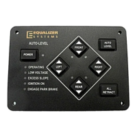
purge the retraction side of the system by pushing the UP Button for each jack or by pressing All
Retract. The jacks may be run in pairs (front pair & rear pair). You will know when the retraction
side of the hydraulic circuit is purged when the fluid level in the reservoir stops and the pump
changes sound (bypass mode). Release the keypad button(s). Repeat this process for the rear jack(s).
Refill the reservoir to full
.
6