a
3) Continue turning the handle until the thicknesser
table reaches its lowest point.
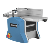
4) On the bottom of the thicknesser table there
are 3 holes, these are the locating holes for the
corresponding locating points on the extraction
port assembly.
5) Make note of “tab a” as this is the point that
engages the interlock switch and allows the
planer thicknesser to run safely.
6) Take care to ensure that this “tab” is located
correctly whilst fitting the dust extraction port.
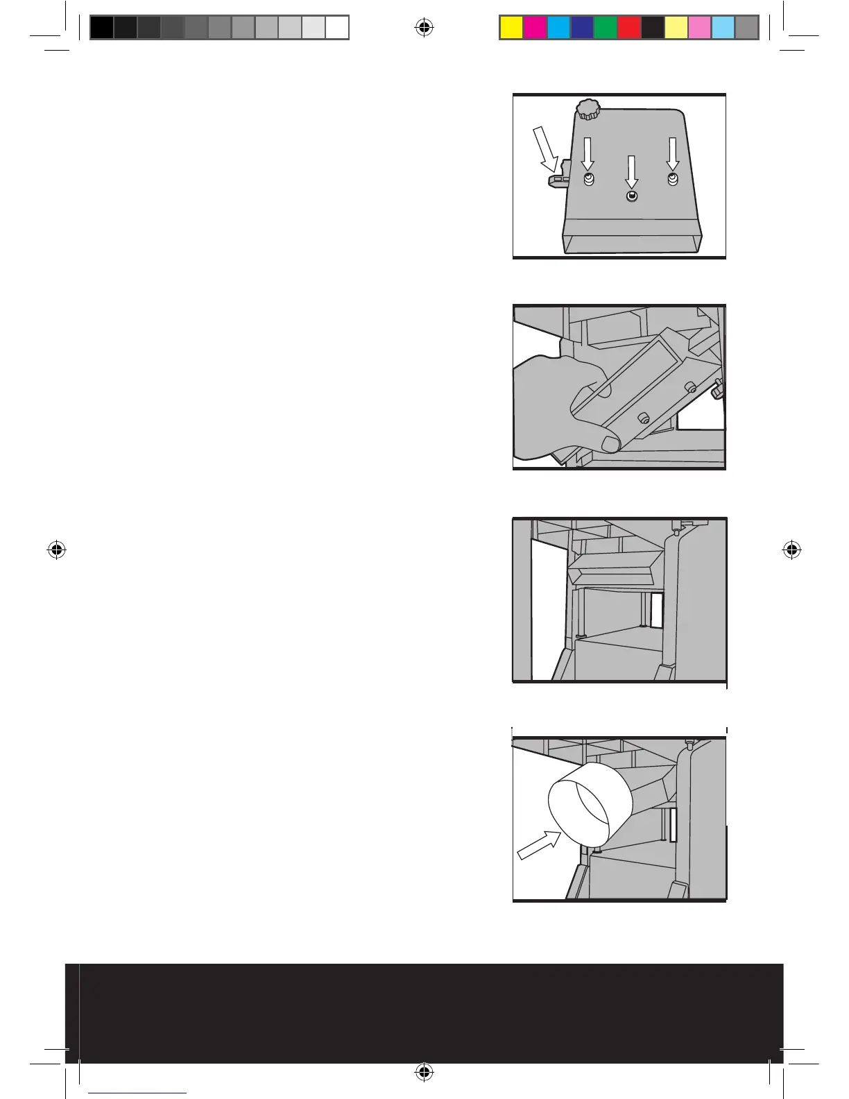
7) Hold the dust extraction port assembly at
approximately 45° and slide it into place onto the
thicknesser bed.
8) Ensure that the 3 locating points line up with
the corresponding holes on the thicknesser bed
and set the port flat against the bed.
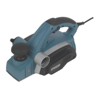
9) Secure the extraction port by fitting and
tightening the supplied nut onto the middle
(threaded) locating point.
10) Turn the height adjusting handle (11) clockwise
to raise the thicknesser bed. This will secure the
extraction port in place as well as engaging the
safety interlock switch.
Caution: Do not secure the extraction port too
tightly If too much force is applied to the height
adjusting handle the extraction port will go
beyond its optimum position, the safety interlock
switch will disengage and the motor will not run.
11) Once fitted correctly, the extraction port should
look as in Fig 16.
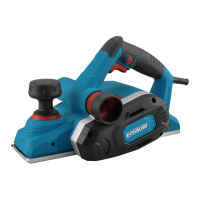
12) Finally, fit the extraction port adapter (E) by
simply sliding it over the extraction port as in
Fig17.
Fig 15
Fig 14
Fig 16
Fig 17