26
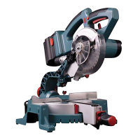
ERBAUER 216MM (8”) SLIDING MITRE SAW
Check for interference between the wood
fence and the lower blade guard. Adjust if
necessary (See fi g 39).
Note: This auxiliary fence is used only with
the saw blade in the 0° bevel position (90° to
the table). The auxiliary wood fence must be
removed when bevel cutting.
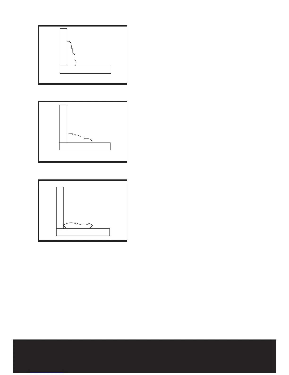
Cutting base molding
Base moldings and many other moldings can
be cut on a compound mitre saw. The setup
of the saw depends on molding characteristics
and applications, as shown. Perform practice
cuts on scrap material. To achieve best results:
1) Always make sure moldings rest fi rmly
against fence and table. Use hold-down or
C-clamps, whenever possible, and place tape
on the area being clamped to avoid marks.
2) Reduce splintering by taping the cut area
prior to making cut. Mark cut line directly on
the tape.
3) Splintering typically happens due to wrong
blade application and thinness of the material
(See fi g 40, 41).
Note: Always perform a dry run cut so you
can determine if the operation being attempted
is possible before power is applied to the saw.
Cutting crown molding
Your compound mitre saw is suited for the
diffi cult task of cutting crown molding. To fi t
properly, crown molding must be compound-
mitreed with extreme accuracy. The two
surfaces on a piece of crown molding that
fi t fl at against the ceiling and wall are at
angles that, when added together, equal
exactly 90°.
Most crown molding has a top rear angle (the
section that fi ts fl at against the ceiling) of 52°
and a bottom rear angle (the section that fi ts
fl at against the wall) of 38°.
In order to accurately cut crown molding for
a 90° inside or outside corner, lay the
molding with its broad back surface fl at on the
saw table.
When setting the bevel and mitre angles for
compound mitres, remember that the settings
are interdependent – changing one changes
the other, as well
(See fi g. 41, 42)
.
mitre at 45°, bevel at 0°
Mitre at 0°, bevel at 45°
F
e
n
c
e
Mitre saw table
Fig 39
Fig 40
F
e
n
c
e
Mitre saw table
F
e
n
c
e
Mitre saw table
Fig 41



 To Next Page