This document describes the ErGear 55" Electric Standing Desk, models EGESD6B-4 and EGESD6V-4. This is an instruction manual for assembling and using the desk, providing details on its components, assembly steps, and controller functions.
Function Description
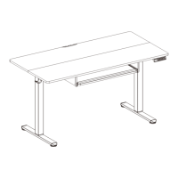
The ErGear 55" Electric Standing Desk is designed to allow users to easily adjust the height of their workspace, promoting a healthier and more dynamic working environment. It features an electric motor for smooth height transitions and a controller with memory presets for convenience. The desk is built to support a substantial load and operate with minimal noise.
Important Technical Specifications
- Height Adjustment Range: 28.3"–46.5" (72–118cm)
- Power Input: 100V–240V
- Max. Speed: 20mm/s
- Operating Noise: <55dB
- Max. Load: 176 lbs / 80 kg
Usage Features
Assembly
The assembly process is divided into five main steps:
- Assembling and Connecting the Desk Legs: This involves attaching the crossbar (01) to the left (02) and right (03) desk legs using bolts (A). The leg bases (04) are then attached to the bottom of the desk legs using bolts (B). This step may require assistance due to the weight of the components.
- Attaching the Side Plates and the Transmission Rod: Side plates (05) are attached to the desk legs using bolts (A). The transmission rod (06) is inserted, and its coupling nut is loosened to allow for height adjustment. Before fully securing, the heights of both desk legs should be measured to ensure they are level. The transmission rod is used to adjust the left leg's height to match the right leg by turning it clockwise to lower or anti-clockwise to raise. Once level, the transmission rod is secured to the motor drive shaft by turning a set screw clockwise, and the coupling nut is tightened.
- Assembling and Attaching the Desktop: The desktop (07) is assembled by inserting wood dowel pins (G) and then attached to the frame using screws (F). A drill or Phillips screwdriver can be used for this step. The controller (08) and storage hooks (H) are also attached to the desktop using screws (F).
- Assembling and Attaching the Keyboard Tray: The keyboard stopper (10) is attached to the keyboard tray (09) using screws (F). The wrist rest (11) is then attached to the keyboard tray. The left (12) and right (13) keyboard tray side plates are aligned and inserted into the keyboard tray. The assembled keyboard tray is then attached to the desk using screws (F), noting the position of the stopper.
- Connecting the Cables: The AC adapter (14) is connected to the desk, and cable clips (J) are used to manage the cables, ensuring a tidy setup.
Controller Functions
The desk's height is controlled via a panel with several buttons:
- Save Current Height Setting: Short-press the 'S' button, and the display will flash. Then, press '1', '2', or '3' to save the current height to that button.
- Select Height Setting 1, 2, or 3: Press the corresponding '1', '2', or '3' button to move the desk to the previously saved height.
- Raise the Desk: Press the 'up arrow' button continuously to raise the desk until it reaches the highest position of 46.5" (118cm) or the button is released.
- Lower the Desk: Press the 'down arrow' button continuously to lower the desk until it reaches the lowest position of 28.3" (72cm) or the button is released.
Maintenance Features
Settings
- Change Display Height Units: Press and hold the 'S' button until 'S-' flashes. Press 'S' again, and 'Un' is displayed. Press 'S' to select, then use the 'up arrow' or 'down arrow' to switch between 'IN' (imperial) and 'SI' (metric). Press 'S' to save.
- Change Collision Force Detection: Long-press the 'S' button until 'S-' shows and flashes. Press 'S' again, and 'Un' is displayed. Use the 'up arrow' or 'down arrow' to switch to 'CF'. Press 'S' to select, then use 'up arrow' or 'down arrow' to choose between 'OFF', 'Low (L)', 'Normal (n)', or 'Heavy (H)' collision force detection. Press 'S' to save.
- Reset: Press and hold the 'down arrow' button for 5 seconds. The screen will show 'RES.' Continue holding until the desk lowers to its lowest level and then slightly rises.
Protection Mode Error Codes
The desk's controller displays error codes to indicate specific issues:
- Hot (Overheating Protection): The motor has been running continuously for 2 minutes and has stopped to prevent damage. Wait at least 18 minutes before further height adjustment.
- E10 (Sensor Malfunction Warning): The motor safety sensor cannot be detected. Power off, check the connection between the motor and controller, then power back on.
- E20 (Overloading Warning): The maximum load has been exceeded. If raising the desk, remove items and try again. If lowering the desk, power off, remove items, power back on, and try again.
- E02 (Operation Status Warning): The desk stops moving due to detected vibration, impact, or incline. If this detection is incorrect, follow the reset instructions before continuing use.
- E32 (Overvoltage Protection): Input voltage is too high. If the correct AC adapter is used, power off the desk, check the connection between power and the controller, then power on again.
- E31 (Undervoltage Protection): Input voltage is too low. If the correct AC adapter is used, power off the desk, check the connection between power and the controller, then power on again.
- E60 (Unequal Leg Height Warning): Power off the desk and check if the left and right legs are at the same height. Adjust if necessary by following the instructions, then power on again.
- (No code) Cable Disconnection Warning: Check motor and controller cable connections. Normal operation should resume once all connectors are properly connected.
The manual also provides technical support contact information for US/CA and UK customers, as well as an email address and website for other inquiries.