EasyManuals Logo

ergoline AFFINITY 660 DYNAMIC POWER Installation Instructions

ergoline AFFINITY 660 DYNAMIC POWER
78 pages
To Next Page IconTo Next Page
To Previous Page IconTo Previous Page
Page #50 background imageLoading...
Page #50 background image
49
Montage
Assembly
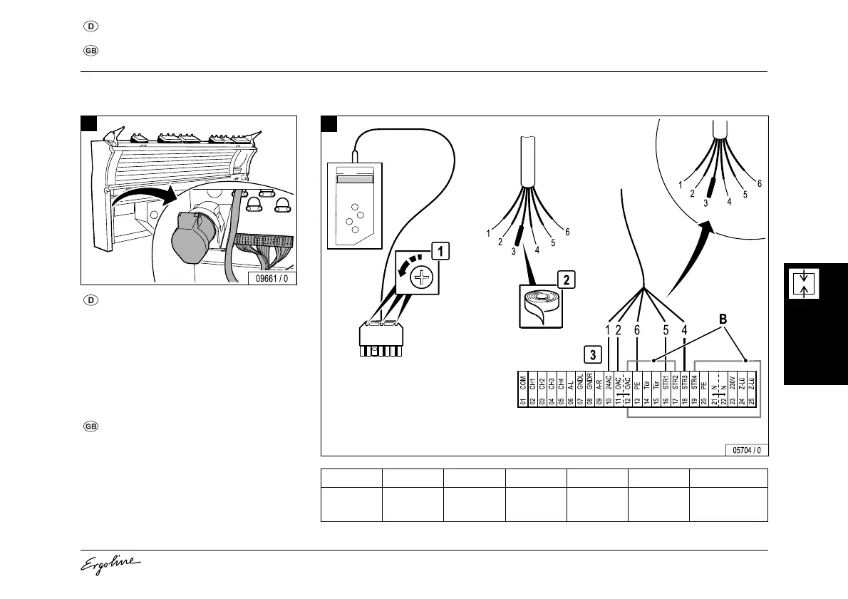
Netzanschluss und Anschluss von Zeitsteuerungen
Mains connection and connection of timers
Netzanschlussleitung durch die Rückwand
zur Steckdose führen und anschließen.
Steuerleitung durch die Rückwand zur
Klemme führen und gemäß Abb. 2 bzw. 3
anschließen.
B = Brücke
Lead the mains connection cable through
the rear wall to the socket and connect.
Lead the control cable through the rear wall
and connect in accordance with fig. 2 or 3.
B = Bridge
1
MCS III plus
Nr./N
o.
123456
Farbe
Colour
rosa
pink
gelb
yellow
weiß
white
braun
brown
grün
green
grün-gelb
green-yellow
2
...

Table of Contents

Other manuals for ergoline AFFINITY 660 DYNAMIC POWER

Questions and Answers:

Question and Answer IconNeed help?

Do you have a question about the ergoline AFFINITY 660 DYNAMIC POWER and is the answer not in the manual?

ergoline AFFINITY 660 DYNAMIC POWER Specifications

General IconGeneral
Brandergoline
ModelAFFINITY 660 DYNAMIC POWER
CategoryTanning equipment
LanguageEnglish

Related product manuals