Do you have a question about the Ergotron WorkFit-D and is the answer not in the manual?
Explains symbols used for safety alerts and their significance to users.
Warns about mounting accessories outside the footprint, potential for injury.
Advises caution with moving parts that can crush or cut during operation.
Do not remove pre-installed stop screws until instructed to avoid lift engine damage.
Keep brake cables away from sync rods and crossbars to prevent restricted lift motion.
Lists all parts included in the product packaging for assembly.
Lists the tools necessary for the installation and setup process.
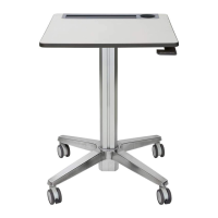
Place worksurface and position the legs, ensuring brake cable is clear.
Set right leg upright and partially attach screws to the worksurface.
Attach one end of the crossbar rod to the right leg as illustrated.
Position left leg, attach rod, and partially secure with screws.
Insert and tighten M5x6 mm screws into the crossbars connecting the legs.
Tighten screws securing legs to the worksurface, avoiding overtightening.
Attach brake cable clips to the bottom of the worksurface using M2.9 x 8 mm screws.
Use cable ties to secure the brake cable to the legs, allowing slack.
CAUTION: Two persons required to safely set the desk upright onto its legs.
Adjust risers on each leg and use a level to ensure the worksurface is even.
Install all equipment, then remove stop screws from legs and brake.
Adjust tension after installation or equipment changes for smooth operation.
Release hand brake, push covers aside, and adjust tension using a 14mm socket wrench.
Guidance on screen height, distance, and angle for optimal ergonomic use.
Tips on breathing, blinking, and taking breaks to reduce eye strain and fatigue.
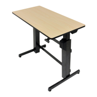
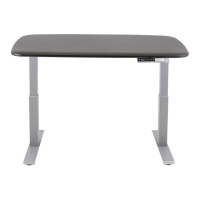
| Product color | Black, Grey |
|---|---|
| Maximum weight capacity | 29.5 kg |
| Depth | 600 mm |
|---|---|
| Width | 1210 mm |
| Height | 78 mm |