5 Baseband Interfaces
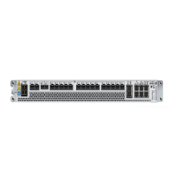
The interfaces for the baseband units are described in Table 7.
Table 7 Baseband 6648 Interfaces
Marking Connector Description Optical
Indicator
(1)
Channels FEC
A
B
ET20 A
(2)(3)(4)
−48 V DC
Power
Yes - -
TN/IDL A
(5)
(6)
QSFP+/QSFP28 4×10 Gbps/4×25 Gbps
Ethernet transmission
External interface; electrical/
optical
Yes 4 RS
(7)(8)
BASE-R
(9)
(8)
TN/IDL B
(6)
TN/IDL C
(6)
TN/IDL D
(6)
SFP/SFP+/SFP28
(10)(11)
1 Gbps/10 Gbps/25Gbps
Ethernet transmission
External interface; electrical/
optical
Yes 1
RS
(7)(8)
BASE-R
(9)(8)
A–M
SFP/SFP+/SFP28
(12)
(13)
Radio interface × 12
Interface between baseband
and external radios, optical
All the ports support CPRI
and eCPRI
Line rates:
—
CPRI: 2.5 Gbps, 4.9
Gbps, 9.8 Gbps, 10.1
Gbps and 24.3 Gbps
—
eCPRI: 10.3 Gbps
and 25 Gbps
(14)
Yes -
RS
(7)(8)
TN E RJ-45 100 Mbps/1 Gbps Ethernet
transmission
External interface; electrical
Yes N/A N/A
SYNC RJ-45 Synchronization interface for
connection of a GNSS
receiver unit, for example,
GRU 04 01
External interface
Yes - -
ALARM 1
ALARM 2
RJ-45 External alarm interface × 2 .
The unit supports eight
external alarms, four per
port.
No - -
SS USB3.1 Type-C for downloading UP from a
memory stick
(15)
No - -
LMT RJ-45 LMT A interface
(16)(17)
LMT B Interface
(17)(18)
Synchronization test
interface
(19)(20)
Internal and external
interfaces
Yes
(21)
- -
- Fault
Optical indicator, red
Yes - -
- Operation
Optical indicator, green
Yes - -
- Maintenance
Optical indicator, blue
For information about the
maintenance button, refer to
Yes - -
Baseband Description
8
271/1551-LZA 701 6001/1 Uen A | 2020-04-29

 Loading...


