Do you have a question about the Ericsson MINI-LINK TN R4 ETSI and is the answer not in the manual?
Provides a general overview of the MINI-LINK TN R4 product family, highlighting its features.
Details the updates and new information introduced in this version of the document.
Gives a brief introduction to the MINI-LINK TN R4 system and its components.
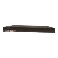
Describes the indoor components and subrack configurations of the MINI-LINK TN R4.
Details the outdoor components of the MINI-LINK TN R4 system.
Explains the system architecture based on the Node Processor Unit (NPU) and backplane buses.
Describes the AMM subrack types, cooling, and power supply functions.
Details the NPU's role in system control, traffic, and management interfaces.
Covers the SAU3's capabilities for DCN, User Input, and Output ports.
Describes plug-in units providing short haul balanced E1 (G.703) interfaces.
Details the SDH portfolio including modems, termination units, and applications.
Explains Ethernet traffic transport over PDH and SDH, and switch functionality.
Discusses ATM traffic aggregation using the AAU for capacity and routing.
Explains the traffic routing function for handling aggregation and interconnections.
Describes protection mechanisms for high availability on various network layers.
Explains synchronization modes and SDH equipment clock functions.
Covers functions for easy operation, maintenance, and handling of plug-in units.
Describes interfacing MINI-LINK E equipment on the same site using SMU2.
Details the E3 interface on SMU2 for unstructured E3 traffic over a 1+1 radio link.
Introduces Radio Terminals providing microwave transmission and modulation schemes.
Details the MMU's role as the indoor part determining traffic capacity and modulation.
Explains the RAU's function in generating, receiving RF signals, and connecting to antennas.
Describes antenna types, sizes, polarization, and installation methods.
Explains Point-to-Multipoint functionality for hub sites and antenna configurations.
Details 1+1 protection configurations for propagation and equipment protection.
Covers transmit power control modes (RTPC, ATPC) and settings.
Explains performance monitoring of the RF Interface according to G.826.
Describes system monitoring, fault localization, and alarm handling mechanisms.
Outlines areas for managing system configuration locally and remotely.
Details performance counters for E1, STM-1, and Ethernet interfaces.
Explains user access, password protection, and security mechanisms for O&M interfaces.
Covers installation and management of License Key Files (LKF) for NE features.
Describes software upgrade procedures, warm restarts, and rollback options.
Details DCN functions, IP services, and DCN interface options.
Provides an overview of management tools like MINI-LINK Craft and ServiceOn.
Describes ICFs for connecting E1 traffic, power, and User I/O to subrack units.
Details the PSU DC/DC kit for converting +24 V DC to –48 V DC for AMM 6p C/D and AMM 20p B.
Covers SFP modules for MMU2 E/F 155 and ETU3, available in electrical or optical.
Explains optical splitters/combiners used with SFPs for EEP solutions.
Describes DCN LAN Switches for connecting multiple equipments to a DCN.
Details the MPH outdoor casing for housing AMM 2p B connected to an RAU.
Describes the TMR 9302 cabinet for housing AMM units and its cooling system.
| Frequency Bands | 6-42 GHz |
|---|---|
| Capacity | Up to 1 Gbps |
| Power Supply | -48 VDC |
| Category | Network Hardware |
| Standard | ETSI |
| Product Type | Microwave Radio |
| Interfaces | Ethernet |
| Modulation | QPSK, 16QAM, 32QAM, 64QAM, 128QAM, 256QAM |