Cabling of Power Connections
To connect the KRD 901 54 the power adapter enclosed is to be used. If Power over
Ethernet is available this may be used instead of powering via the power adapter
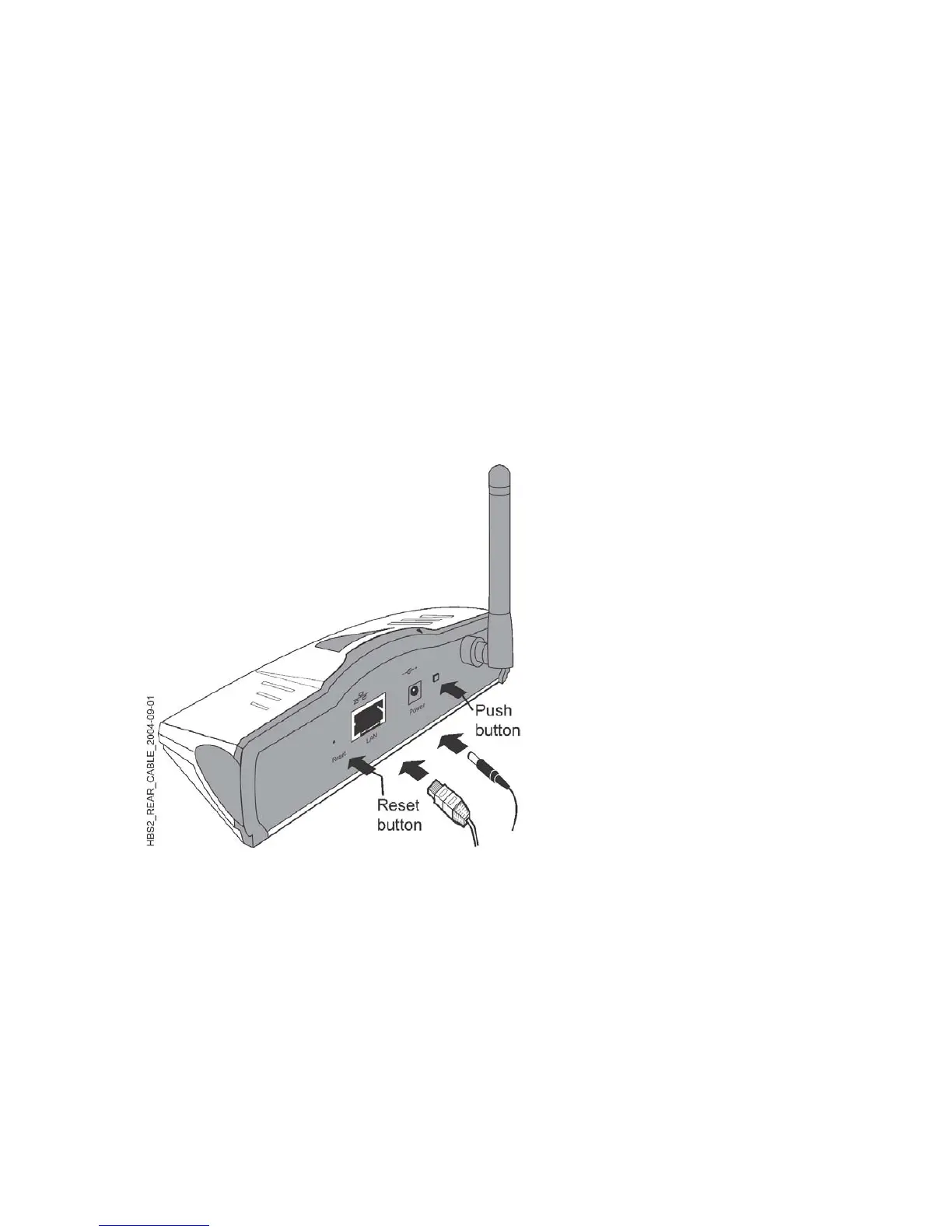
cable. The power cable and the Ethernet cable to the IP Access Network shall be
connected as shown in Figure 4 below.
Buttons on rear panel of KRD 901 54
On the rear panel a push-button is placed. Pressing the button once will start the
member pairing sequence. Pressing the button twice (like a double click using a
“mouse”) will start the guest pairing sequence (i.e. being a guest at the premises
of another “Member”). See Figure 4.
Also a Reset function can be activated from the rear panel by using a thin pointy
device for at least 3 seconds. Activating the reset button will set the KRD 901 54 up to
the factory default settings; i.e. the PIN code and clearing the pairing list. See
Figure 4.
Figure 4 Cable connections
4
 Loading...
