Do you have a question about the Ericsson LPE-200 and is the answer not in the manual?
Radio specifications including FCC ID, input voltage, frequency, dimensions, weight, and temperature.
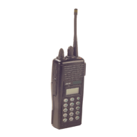
Highlights features like compact size, ruggedness, dual mode, display, and controls.
Lists available batteries, chargers, carrying accessories, and audio accessories with part numbers.
Describes controls like knobs, emergency button, PTT, Clear/Monitor, and Option buttons.
Details functions of A/D, OPT, and SCN keys in Scan mode.
Explains functions of numbered keys, OPT, M, and other keys in System mode.
Describes microprocessor software, bootloader, FLASH application, and DSP software.
Details the RX Front End circuitry, including filters, amplifiers, and mixer.
Details the N150 chip's functions in transmit offset, SSB mixing, and modulation.
Describes the main and auxiliary synthesizers for generating LO frequencies.
Explains the synthesizer, receiver, and transmit regulators.
Lists essential equipment for programming and testing the radio.
Details personality and flash programming steps.
Provides a table of symptoms, possible causes, and actions for common radio issues.
Describes the general format of error messages and the meaning of fatal errors.
Lists hardware-related fatal errors that cause radio resets.
Lists fatal software errors that require service if resets don't resolve them.
Lists non-fatal software errors that appear briefly during operation.
Categorizes programming errors into low-level communication routines and bootloader errors.
Lists errors that can occur on the PC side during programming.
Step-by-step instructions for removing the battery pack and front cover.
Details separating boards and removing the switch assembly from the radio housing.
Covers PA module and filter replacement, and general reassembly instructions.
Lists parts for the LPE-200 radio, including front and rear assemblies.
Details components of the front assembly for the Scan model.
Lists components for the front assembly of the System model.
Details the parts for the rear assembly of the radio.
Lists components and their part numbers for the main circuit board.
Shows the layout of components on the front side of the 900 MHz circuit board.
Illustrates the component placement on the back side of the 900 MHz circuit board.
A high-level block diagram showing the main functional blocks of the transceiver.
| Number of Channels | 16 |
|---|---|
| Modulation | FM |
| Battery Life | 8-10 hours |
| Channel Spacing | 12.5/25 kHz |
| RF Output Power | 5 W |
| Power Source | Rechargeable battery |