Interfaces
Connection
Description
Connector Type
G.703-1 Transmission Link 1 15-pin female, D-sub
G.703-2 Transmission Link 2 15-pin female, D-sub
G.703-3 Transmission Link 3 15-pin female, D-sub
G.703-4 Transmission Link 4 15-pin female, D-sub
DC out +24 V DC to external
equipment
3-pole female, D-sub
External Alarms External alarm inputs from
DF
37-pin female, D-sub
ESB-1 ESB to co-sited cabinets 9-pin female, D-sub
ESB-2 ESB to co-sited cabinets 9-pin female, D-sub
FCU RD Optical cable connector
from the BBS
Opto connector
+24 V DC DC filter Cable clamp
Earth Earth stud M8 to main earth
cable
M8 stud
ACCU Mains connection to
PSU-AC
Screw terminal
DCCU
0
48 V connection to
PSU-DC
Screw terminal
ASU Antenna sharing
connections
SMA-connector
TMA-CM DC power supply through
bias injectors to the TMAs
SMA-connector
DXX Transmission link TNC-connector
GPS Synchronization signal from
GPS antenna
9-pin female, D-sub
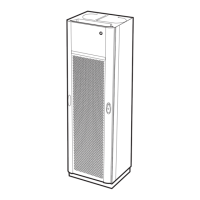
7.2 RBS 2206 V2 External Connections
This section describes the external connections of the RBS 2206 V2.
The RBS does not have connection fields on the upper right- and left-hand
sides of the cabinet. Cables are instead connected directly to the DXU.
23
19/1551-LZA 701 0001 Uen PG1 | 2010-10-08
 Loading...