Do you have a question about the Ericsson RBS 6401 and is the answer not in the manual?
The Ericsson RBS 6401 is a Radio Base Station (RBS) designed for wireless communication networks, serving as a crucial component in providing cellular coverage. This installation guide outlines the necessary steps for deploying the RBS 6401, covering unpacking, mounting, cabling, and verification, along with optional procedures for ceiling installation and external antenna integration.
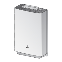
The RBS 6401 functions as a transceiver that connects mobile devices to the core network. It receives signals from mobile phones, processes them, and transmits them to the network, and vice versa. The device supports various connection options for data transmission, including WAN A (Ethernet), DSL (VDSL2), and WAN B (Ethernet optical cable), allowing flexibility in network integration. It also features an external alarm port for monitoring and reporting system status, and a GPS cable connection for precise timing and location services, essential for network synchronization and handover procedures. The RBS 6401 is designed to be a compact and efficient unit, capable of being installed in various environments, including wall and ceiling mounts, and can be configured with internal or external antennas to optimize coverage and performance.
The installation process for the RBS 6401 is structured to be straightforward, beginning with unpacking and a visual inspection for any damage. A key usage feature is the integration with the ENIS Android application, which allows for scanning the barcode on the back of the RBS with a smartphone. This likely facilitates inventory management, configuration, and potentially diagnostic checks, streamlining the deployment process.
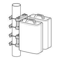
Mounting the RBS 6401 involves a detailed procedure to ensure secure and correct placement. The guide provides instructions for wall mounting, which includes using a drilling template to mark precise locations for screws. The mounting bracket is then attached to the wall, and the RBS is hung and fastened securely. For horizontal ceiling installations, an additional ceiling plate is required, which is installed between the ceiling and the mounting bracket. This flexibility in mounting options allows the RBS to be deployed in diverse indoor environments, adapting to architectural constraints.
Cable connection is a critical step, with clear instructions for connecting power, data (WAN A, DSL, WAN B), external alarm, and GPS cables. The design includes cable strain relief for the AC power cable, which helps prevent damage to the cable and connector over time. The guide emphasizes connecting all other cables before the power cable, a standard safety and operational practice. The RBS also supports external antenna integration, which involves removing the front cover, breaking out aluminum knock-outs, inserting adapter cables, and connecting them to the internal connectors. This feature allows for enhanced signal coverage and performance, particularly in challenging RF environments or when specific antenna patterns are required.
After installation, the RBS 6401 features an operational indicator (green light) to confirm proper functioning and the absence of active alarms. This visual feedback is crucial for quick verification of successful deployment. In case of errors or active alarms, the user is directed to a "Handling Faults On-Site" document, indicating a structured approach to troubleshooting.
While the manual primarily focuses on installation, several aspects hint at maintenance considerations. The instruction to "Always clean optical cable connectors before connecting them" is a direct maintenance practice aimed at preventing signal degradation and ensuring optimal performance of fiber optic connections. This highlights the importance of cleanliness in optical fiber systems to avoid issues caused by dust or debris.
The provision of an external alarm port suggests a capability for remote monitoring and fault reporting. By connecting an external alarm cable, the RBS can communicate its status to a centralized monitoring system, enabling proactive maintenance and rapid response to issues. This feature is vital for minimizing downtime and ensuring network reliability.
The ability to install external antennas implies a modular design that could facilitate antenna upgrades or replacements without needing to replace the entire RBS unit. This modularity can simplify maintenance tasks and extend the operational life of the equipment.
The mention of a "Handling Faults On-Site" document indicates that Ericsson provides structured guidance for diagnosing and resolving common issues that may arise after installation. This resource is a key maintenance feature, empowering field technicians to perform troubleshooting efficiently.
Furthermore, the requirement for specific tools, such as a torque wrench with an 18 mm fastening bit for external antenna installation, underscores the importance of precise assembly to ensure long-term reliability and performance. Proper torque application prevents over-tightening or under-tightening, which could lead to component damage or loose connections over time.
The general advice to "Dispose of waste according to local regulations" after installation also touches upon environmental maintenance and responsible end-of-life management for packaging and potentially old components.
In summary, the Ericsson RBS 6401 is designed for efficient deployment and reliable operation in cellular networks. Its features support flexible installation, straightforward cabling, and clear operational verification, while underlying maintenance considerations emphasize cleanliness, remote monitoring, modularity, and structured troubleshooting.
| Cooling | Passive |
|---|---|
| Product Type | Radio Unit |
| Frequency Bands | LTE Band 1, 3, 7, 8, 20, 28, 38, 40, 41 |
| MIMO | 2x2 |
| Power Supply | 48V DC |
| Connectivity | Ethernet |
| Mounting | Wall or Pole |
| Operating Temperature | -40°C to +55°C |