8.6 Electric wiring
8.6.2 Power supply specification
Table 8-6
Outdoor power supply
Power
supply
Manual
switch
Fuse Wiring
Item
Model
380-415V
3N~50Hz
50A 36A
10mm
2
(<20m)
1. No additional control components are required in the electric
cabinet (such as relay, and so on), and the power supply and
control wires not connected with the electric cabinet are not
allowed to go through the electric box. Otherwise, electromagnetic
interference may cause failure of the unit and control components
2. All cables led to the electric box should be supported
independently but by the electric box.
3. The strong current wires generally pass the electric box, and
220-230V alternating current may also pass the control board, so
wiring connection should conform to the principle of separation of
strong current and weak current, and the wires of power supply
should be kept more than 100 mm away from the control wires.
4. All electric wires must conform to local wiring connection norm.
The suitable cables should be connected to power supply terminal
through wiring connection holes at the bottom of the electric
cabinet. According to Chinese standard, the user is responsible for
providing voltage and current protection for the input power supply
of the unit.
8.6.3 Requirements of wiring connection
5. All power supplies connected to the unit must pass one
manual switch, to ensure that the voltages on all nodes of
electric circuit of the unit are released when the switch is cut off.
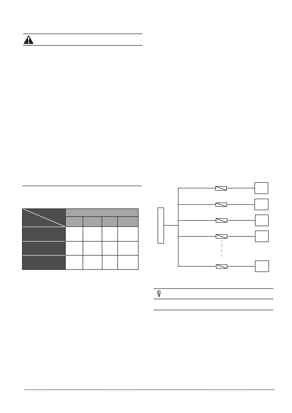
6. The cables of correct specification must be used to supply
power for the unit. The unit should use independent power
supply, and the unit is not allowed to use the same power supply
together with other electric devices, to avoid over-load danger.
The fuse or manual switch of the power supply should be
compatible with working voltage and current of the unit. In case
of parallel connection of multiple modules, the requirements of
wiring connection mode and configuration parameters for the
unit are shown in the following figure.
7. Some connection ports in the electric box are switch signals,
for which the user needs to provide power, and the rated voltage
of the power should be 220-230VAC. The user must be aware
that all power supplies they provided should be obtained through
power circuit breakers (provided by the user), to ensure that all
voltages on the nodes of the provided power supply circuit are
released when the circuit breakers are cut off.
8. All inductive components provided by the user (such as coils
of contactor, relay, and so on) must be suppressed with standard
resistance-capacitance suppressors, to avoid electromagnetic
interference, thus leading to failure of the unit and its controller
and even damages to them.
9. All weak current wires led to the electric box must apply
shielded wires, which must be provided with grounding wires.
The shield wires and power supply wires should be laid
separately, to avoid electromagnetic interference.
10. The unit must be provided with grounding wires, which are
not allowed to be connected with the grounding wires of gas fuel
pipelines, water pipelines, lightning conductors or telephones.
Improper earth connection may cause electric shock, so please
check whether earth connection of the unit is firm or not
frequently.
Outdoor power supply
Outdoor
unit 1
Outdoor
unit 2
Outdoor
unit 3
Outdoor
unit 4
Outdoor
unit N
Manual switch
Manual switch
Manual switch
Manual switch
Manual switch
Only 16 Modular units can be combined at most.
NOTE
8.4 Wiring steps
Step 1. Check the unit and ensure that it is connected with
grounding wires correctly, to avoid leakage, and the grounding
devices should be mounted in strict accordance with the
requirements of electrical engineering rules. The grounding
wires can prevent electric shock.
Step 2. The control box of the main power switch must be
mounted in a proper position.
Step 3. Wiring connection holes of the main power should be
provided with glue cushion.
Step 4. The main power and neutral wires and grounding
wires of power supply are led into the electric box of the unit.
Figure 8-21
8.6.1 Electric wiring
1. The air-conditioner should apply special power supply, whose
voltage should conform to rated voltage.
2. Wiring construction must be conducted by the professional
technicians according to the labeling on the circuit diagram.
3. The power wire and the grounding wire must be connected
the suitable terminals.
4. The power wire and the grounding wire must be fasten up by
suitable tools.
5. The terminals connected the power wire and the grounding
wire must be fully fastened and regularly checked, in case to
become flexible.
6. Only use the electric components specified by our company,
and require installation and technical services from the
manufacturer or authorized dealer. If wiring connection fails to
conform to electric installation norm, failure of the controller,
electronic shock, and so on may be caused.
7. The connected fixed wires must be equipped with full
switching-off devices with at least 3mm contact separation.
8. Set leakage protective devices according to the requirements
of national technical standard about electric equipment.
9. After completing all wiring construction, conduct careful check
before connecting the power supply.
10. Please carefully read the labels on the electric cabinet.
11. The user’s attempt to repair the controller is prohibited, since
improper repair may cause electric shock, damages to the
controller, and so on. If the user has any requirement of repair,
please contact the maintenance center.
12.The power cord type designation is H07RN-F.
CAUTION
ECH060N
380-415V
3N~50Hz
100A 70A
25mm
2
(<20m)
ECH090N
380-415V
3N~50Hz
125A 100A
25mm
2
(<20m)
ECH030N
32
 Loading...