The connection of control of pump of ECH090N is different with ECH030N and ECH060N.
An all-pole disconnection device which has at least 3mm separation distance in all pole and a residual current
device(RCD)with the rating of above 10 mA
shall be incorporated in the fixed wiring according to the national rule.
The appliance shall be installed in accordance with national wiring regulationgs.
CAUTION
Step 5. The wires of the main power must pass the bonding clamp.
Step 6. Wires should be connected firmly to the connection terminals L1, L2, L3and N.
Step 7. Phase sequences must be consistent when the wires of the main power.
Step 8. The main power should be located out of easy reach of non-professional maintenance personnel, to avoid mal-operation and
improve safety.
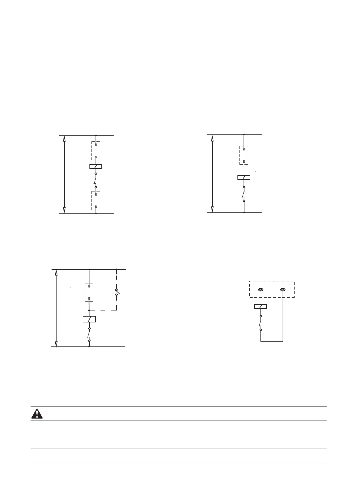
Step 9. ECH030N and ECH060N connection of control wires of auxiliary electric heaters: the control wires of AC contactor of the
auxiliary electric heater must pass the connection terminals CN19_L and CN19_N of the main unit, as shown in Fig. 8-22-1. Step
10.ECH090N connection of control wires of pipeline auxiliary electric heaters: the control wires of AC contactor of the pipeline auxiliary
electric heater must pass the connection terminals HEAT1 and COM of the connector XT1 in the electric box of the unit. as shown in
Fig. 8-22-2.
Step 11. ECH030N and ECH060N Connection of control wires of pump: the control wires of AC contactor of pump must pass the
connection terminals CN1 or CN2 of the main unit, as shown in Fig. 8-22-3.
Step 12. ECH090N Connection of control wires of pump: the control wires of AC contactor of pump must pass the connection terminals
PUMP and N of the connector XT1 in the electric box of the unit, as shown in Fig. 8-22-4.
Step 13. The connection way of the wire controller connects with every signal wires from package units: signal wires P, Q, E are
connected in the same way of main wires connection method and accordingly connect to the terminals P, Q, E in the wire controller.
COM
Power supply (220-240V~50Hz)
Control coil of 3 phase AC contactor
L1/L2/L3
N
HEAT1
Overcurrent relay
Fig. 8-22-1
CN19_L
Power supply (220-240V~50Hz)
Control coil of 3 phase AC contactor
CN19_N
Overcurrent relay
L1/L2/L3
N
Connetcor XT1 in the electric box
Fig. 8-22-2
Power supply (220-240V~50Hz)
Overcurrent relay
Control coil of 3 phase AC contactor
Switch (For trial run of pump)
CN2 or
CN1
L1/L2/L3
N
Fig. 8-22-3
PUMP N
Connector XT1 in the electric box
Control coil of 3 phase AC contactor
Overcurrent relay
Fig. 8-22-4
33