26
KAPITTEL 4 BRUK
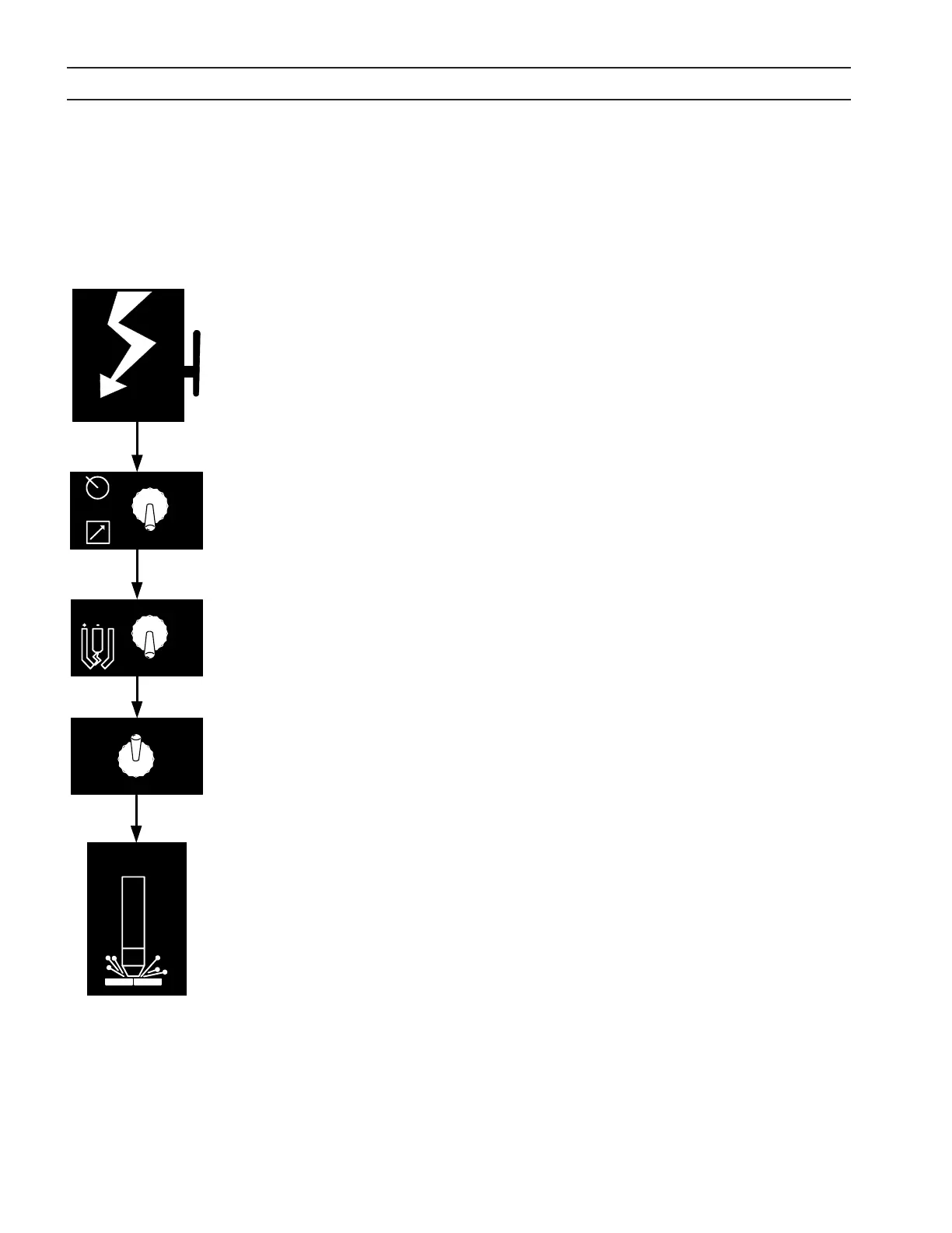
1. Tilkople nettstrøm ved å sette den eksterne skillebryteren til PÅ. (EPP-400 har ingen
AV/PÅ-bryter). Nettspenningsindikatoren MAIN POWER vil lyse, og feilindikatoren
FAULT vil blunke for deretter å slukke.
2. Velg innstilling for venderen PANEL/REMOTE.
3. Still inn venderen PILOT ARC HIGH/LOW. Hvis Pilot arc High / Low velges fra en
ernkontroll, må bryteren være i lav-stilling. (Se skjæredata i brennerhåndboken).
4. I PANEL-modus, se på forhåndsinnstilt strøm ved hjelp av ACTUAL AMPS / PRESET
AMPS-venderen (ACTUAL=virkelig, PRESET=forhåndsinnstilt). Juster strømmen inntil
omtrentlig ønsket verdi vises av amperemeteret. I ernstyringsmodus, hvis ACTUAL
AMPS / PRESET AMPS-venderen er satt til PRESET AMPS, vises utgangsstrømmen
ernkontrollen vil begynne med.
5. Start plasmaskjæreoperasjonen. Dette kan inkludere andre manuelle
forhåndsinnstillinger, avhengig av den totale plasmapakken.
6. I PANEL-modus, etter at skjæringen har begynt, juster strømmen til ønsket verdi.
7. Hvis skjæring eller avmerking ikke vil starte opp, sjekk om feilindikatoren FAULT
lyser. Hvis den lyser, se feilsøkingskapitlet.
Merknad:
Feilindikatoren FAULT blinker når kontaktoren skrus på første gang, noe
som betyr at likestrømsbussen starter opp på normal måte.
4.3 Funksjonsrekkefølge
SECTION 4 Operation
ESP 400C Plasma Power Source
ESP 400C Plasma Power SourceESP 400C Plasma Power Source
ESP 400C Plasma Power Source
4-4
Begin
Cutting
ACTUAL AMPS
PRESET AMPS
HIGH
LOW
PILOT
ARC
PANEL
REMOTE
Apply Power
4.3 Sequence of Operation
1. Apply power by closing the line (wall) switch.
(The ESP-400C does not have an on/off
switch). The main power light will illuminate
and the fault light will flash and then go out.
2. Select the Panel/Remote setting.
3. Set pilot arc High/Low switch. (Refer to cutting
data in the torch manual.)
4. If using panel mode, view preset amps with the
ACTUAL/PRESET AMPS switch. Adjust current
until the approximate desired value is shown on
the ammeter.
5. Begin plasma cutting operation. This may
include manually setting up other options,
depending on the total plasma package.
6. If using panel mode, after cutting has begun,
adjust current to desired amount.
7. Check for fault light. If a fault light illuminates,
refer to troubleshooting section.
Note: The fault light flashes when the contactor is
Note: The fault light flashes when the contactor isNote: The fault light flashes when the contactor is
Note: The fault light flashes when the contactor is
first turned on signifying the DC Bus powered up
first turned on signifying the DC Bus powered upfirst turned on signifying the DC Bus powered up
first turned on signifying the DC Bus powered up
normally.
normally.normally.
normally.
4.4 Arc Initiation Settings
The time to achieve full current can be adjusted to
suit your particular system. This feature uses 50%
of the cutting current to start, dwell and then
gradually (less than a second) achieve full current.
The ESP-400C is factory shipped with this feature
enabled. The default settings are:
Minimum Start Current 40A
Start Current 50% of cut current
Timing to achieve full current 800 msec
Dwell Time 50 msec