44
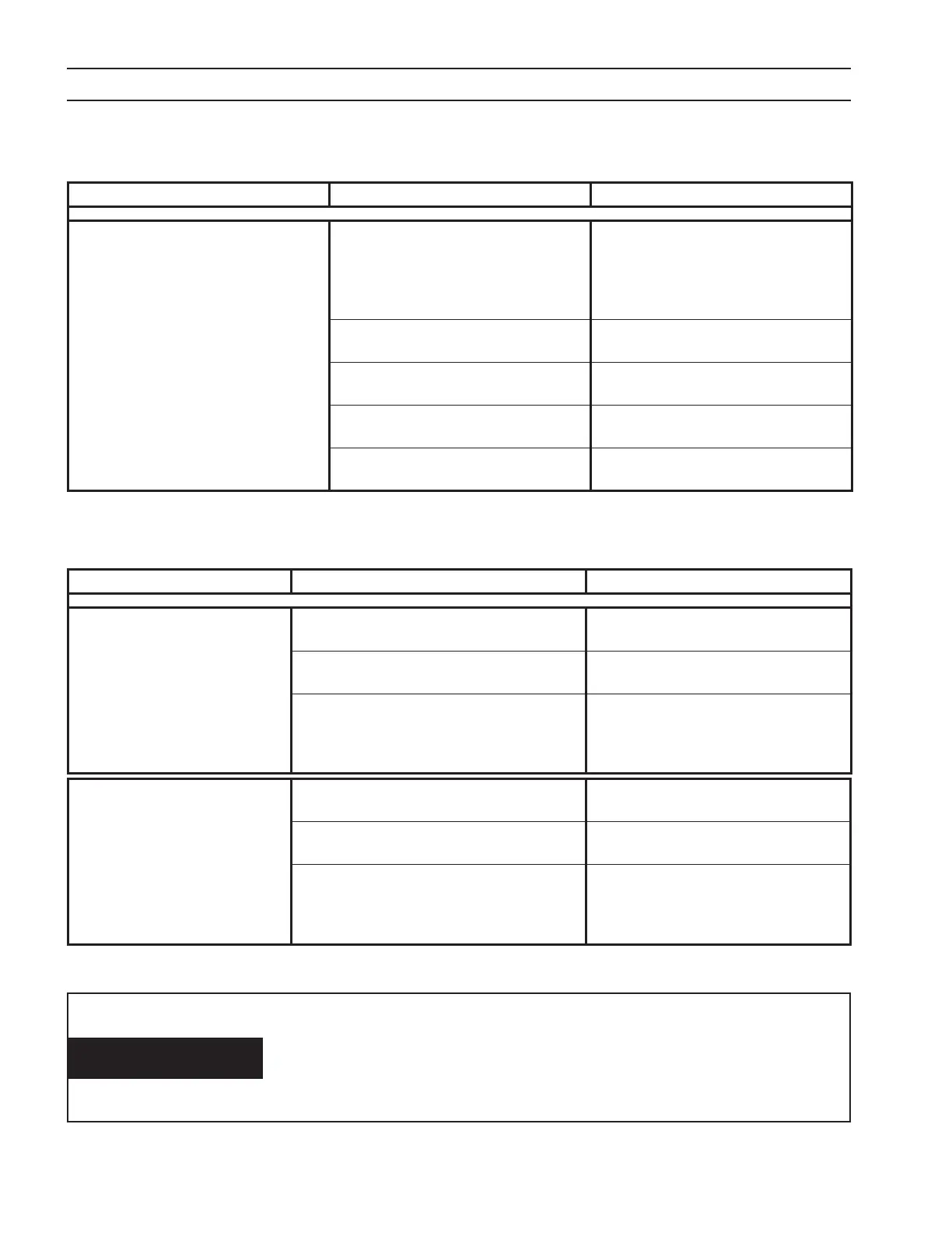
Problem Possible Cause Action
Fuses F1 and F2 blown.
Process controller ignites pilot arc too
soon after providing the “Contactor
On” signal
Process controller must allow at least
300MS to lapse between the applica-
tion of the “Contactor On” signal and
the ignition of the pilot arc. Fix process
controller logic and replace diodes.
Faulty negative (Electrode) output cable
shorting to earth ground.
Repair cable
Shorted freewheeling diode.
Replace shorted freewheeling diode
and F1-F2
One or more shorted diode rectiers
(D13-D18) on “POS Plate”.
Replace all diode rectiers on the “POS
Plate”.
One or more shorted diode rectiers
(D7-D12) on “NEG Plate”.
Replace all diode rectiers on the “NEG
Plate”.
SECTION 6 TROUBLESHOOTING
6.3.5 Fuses F1 and F2 Blown
Problem Possible Cause Action
Works OK at 275A or less - Over
current right side when cutting
over 275A. LED 6 on control board
illuminated.
Loose or unplugged connector at left PWM /
Drive PCB (PCB2)
Secure connector
Faulty left PWM / Drive PCB
Replace right PWM / Drive PCB P/N
0558038308
Check voltage between P5-1 and P5-2 at the
left PWM / Drive PCB (PCB2). Should be 20V
AC. Between P5-1 and P5-3 should be 40V AC.
If not the control transformer (T5) is faulty.
Replace control transformer T5
6.3.6 Intermittent, Interrupted or Partial Operation
NEVER attempt to power-up or operate the power source with any
Gate / Emitter IGBT Plug disconnected from it’s PWM / Gate Drive
Board. Attempting to operate the power source with any open (un-
plugged) IGBT Gate / Emitter Connector may damage the IGBT and
the plasma cutting torch.
CAUTION
Works OK at 275A or less - Over
current left side when cutting
over 275A. LED 9 on control board
illuminated.
Loose or unplugged connector at Right PWM
/ Drive PCB (PCB3)
Secure connector
Faulty Right PWM / Drive PCB
Replace right PWM / Drive PCB P/N
0558038308
Check voltage between P5-1 and P5-2 at the
right PWM / Drive PCB (PCB3). Should be 20V
AC. Between P5-1 and P5-3 should be 40V AC.
If not the control transformer (T7) is faulty.
Replace control transformer T7