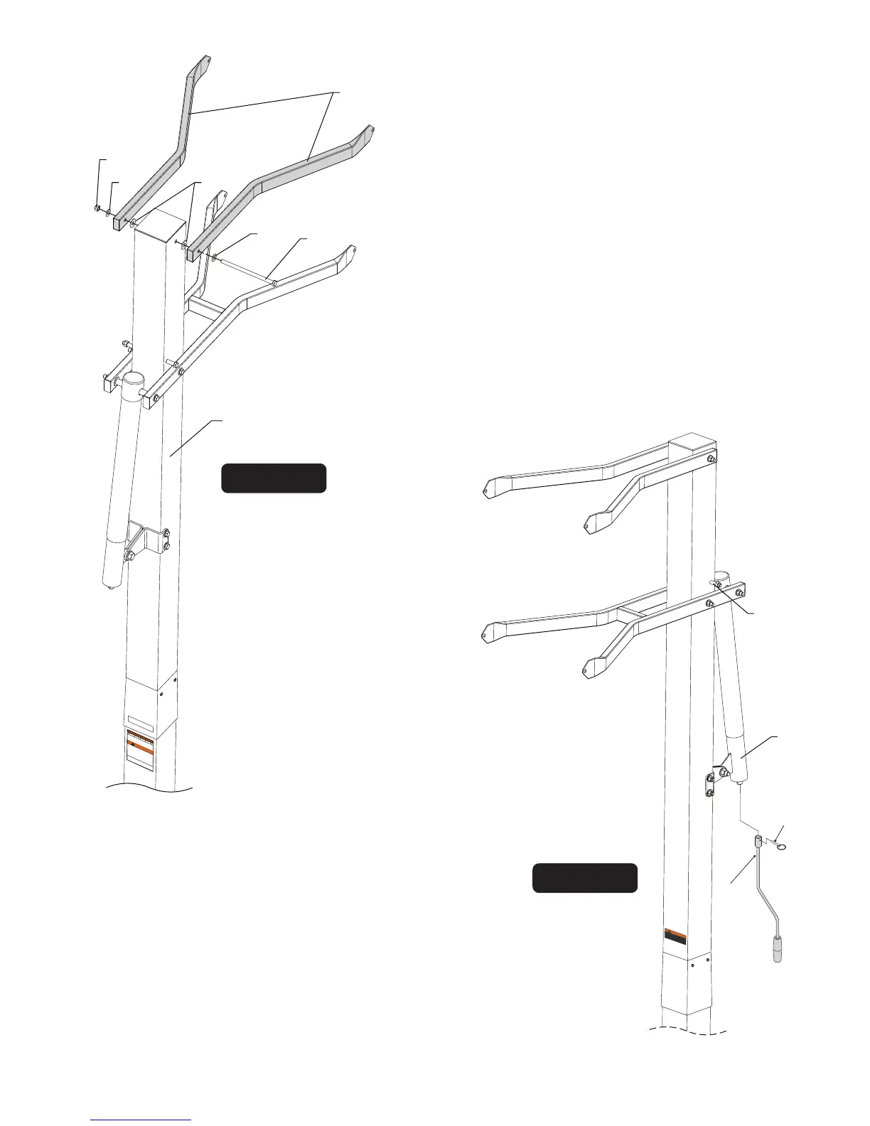
15. Attach of Upper Arms (#6) to Top Pole (#3), as shown
in
two spacers (#8) and one lock nut (#4).
Note: Tighten bolts snug but, do not over tighten.
Board Arms must pivot freely
16. Slide Actuator Handle (#35) onto shaft on the bottom of
Actuator (#16). Line up hole in shaft with hole in Actuator
Handle and insert Pin (#34) to secure. See Figure 12.
17. To aid in the assembly of the backboard, lower the backboard,
by turning the Actuator Handle, until the lower arm makes
contact with Stop Spacer (#10).
Figure 12
6
7
18
818
4
3
Figure 11
16
Stop Spacer
(#10)
35
34
Figure 11, using a bolt (#7), two flat washers (#18),
FAILURE TO FULLY ENGAGE THE
BOTTOM OF THE UPPER POLE TO
THE 6” MARK ON THIS BOTTOM
POLE STICKER, COULD CAUSE
YOUR UNIT TO COLLAPSE AND MAY
RESULT IN SERIOUS INJURY OR
PROPERTY DAMAGE.
BACKSIDE
Bottom
of upper pole
must
cover
the
above
orange portion of this
sticker
(6” mark).
WARNING
!
4L-8151-00
BACK SIDE
DO NOT DUNK ON THIS UNIT .
DO NOT HANG FROM ANY PART OF THIS
UNIT , INCLUDING THE BACKBOARD, RIM,
SUPPORT BRACES OR NET
.
4L-8152-00
WARNING
12