20.
21. Place a level across rim assembly and adjust rim until it is
level. Finish tightening the four nuts.
NEVER USE RIM WITH COVERPLATE REMOVED!
Figure 14
41
27
37
28
38
4
26
32
33
40
42
42
14
Detail A
Pad #37 & #38
Screw #42
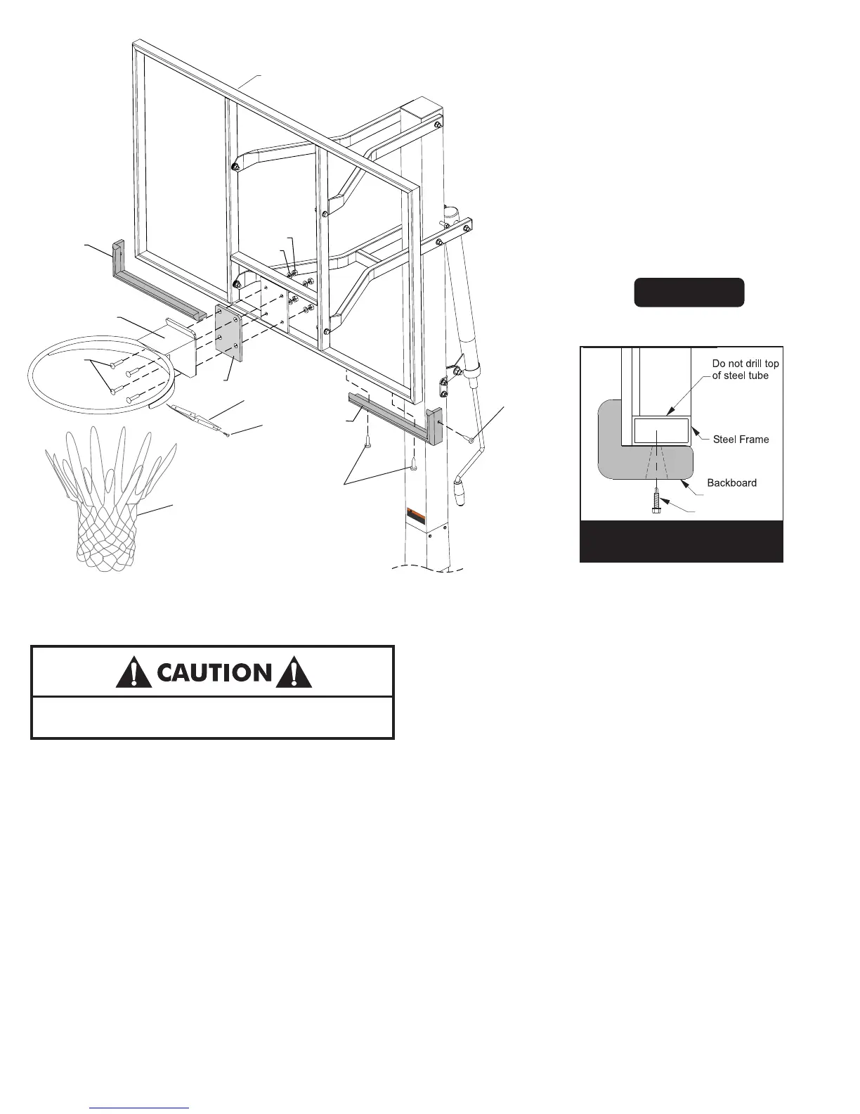
22. Attach Rim Cover Plate (#32) using four screws (#33). See
23. Check all nuts and bolts and make sure everything is
tightened properly. DO NOT over tighten pivot points,
snug is tight enough.
24. Use the Backboard Pads (#37) and (#38) as a template and
mark the hole locations on the backboard frame. See Figure
14 and Detail A.
25. Drill 9/64" pilot holes into steel backboard frame. See
Detail A. Do not drill through both sides of tube.
26. Secure Backboard P
ads (#37) and (#38), as shown, using
screws (#42). Note: Tighten screws tight but, do not over
tighten.
Figure 14.
Note: Cordless drill recommended for screw installation.
Do not over tighten screws causing screws to strip.
Note: To install screws, it will be easier if you use a
cordless drill with 5/16” socket (instead of Phillips head).
Mount Goal Assembly (#28) and Rim Pad (#27) to
Backboard, as shown in Figure 14, using four bolts (#41),
four washers (#26), and four locknuts (#4). Tighten
fasteners, but leave them loose enough to level rim.
DO NOT DUNK ON THIS UNIT .
DO NOT HANG FROM ANY PART OF THIS
UNIT , INCLUDING THE BACKBOARD, RIM,
SUPPORT BRACES OR NET
.
4L-8152-00
WARNING
!
Note: Screws (#42), used in step 26, are Self Drilling
screws and can be installed without drilling pilot holes.
However, it will be easier to install screws if you drill
9/64” pilot holes. WEAR SAFETY GLASSES if drilling holes.
Note: Make sure (#27) Rim
Pad is installed between Rim
(#28) and Backboard (#23)
23
Note: Make sure (#27) Rim Pad is installed
between Rim (#28) and Backboard (#23)