31
D INSTALLING THE ELECTRICITY AND GAS TO THE APPLIANCE
In order to install gas to the replace, check the operang pressure or install the network cable, the glass and
burner tray needs to be removed.
Power Supply
While the cavity is being created, consideraon must be given to the locaon of an appropriate power supply.
An earthed 230/240 volt mains power connecon (typically a standard 3 pin outlet) must be available within 1m
of the boom right of the appliance. This connecon must be accessible aer the heater has been fully installed
so that the appliance can be safely disconnected from the mains power supply prior to servicing.
A mains isolaon switch (compliant to AS:NZS 5601 Clause 6.2.8) which is accessible from outside the cavity can
also be used to disconnect the power.
Regardless of the method used, it MUST ALWAYS be possible to safely isolate the electrical supply to the
appliance aer it has been fully installed.
This appliance must not be located immediately below a socket outlet. This appliance will draw a maximum of 2
Amps from a 230/240V supply. No addional power supply is required for the Power Flue.
An electrical wiring diagram is located underneath the electronic tray, and also in the rear of this manual
(Service Secon S13 on page 59).
Removing the Glass
The DF-Series replace has two layers of glass: the inner glass seals the rebox and is called the primary glass;
the outer glass is called the secondary glass.
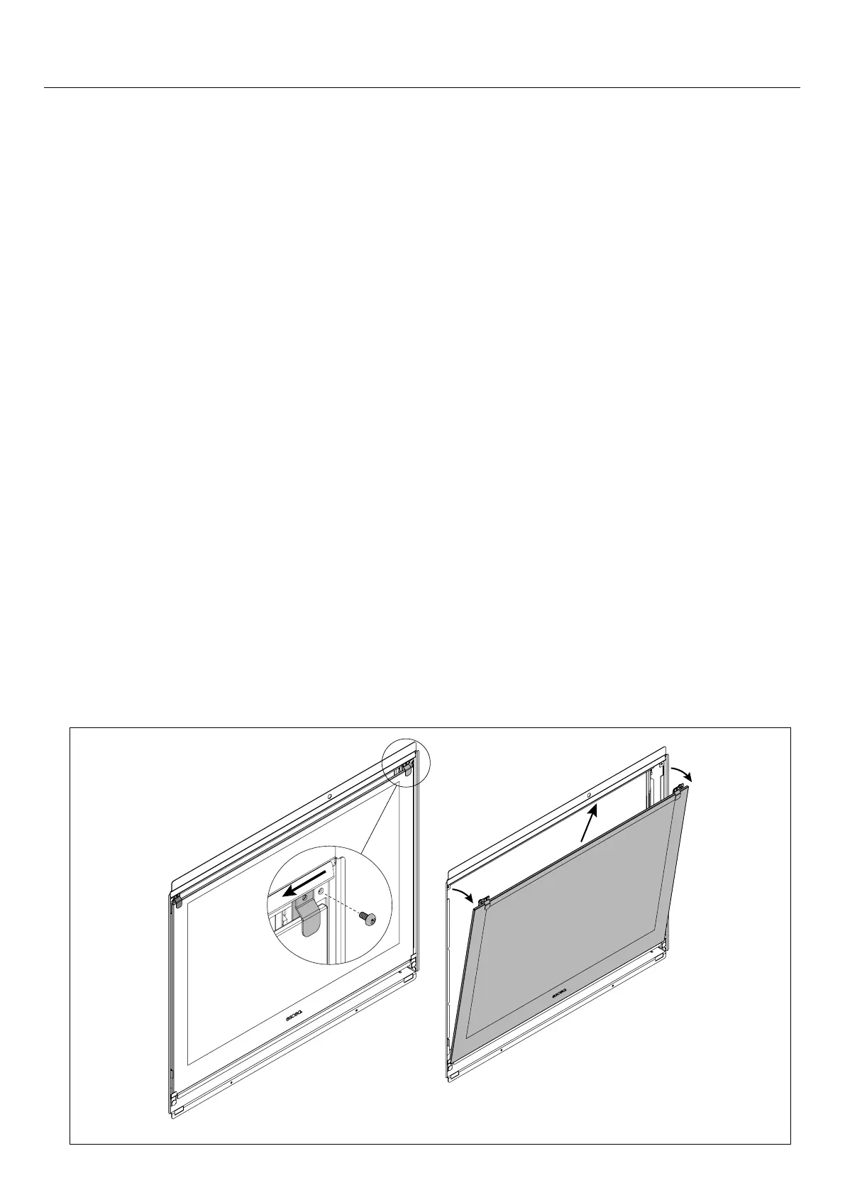
Secondary Glass
Unscrew the secondary glass retainers and slide them towards the middle of the re.
Tilt the glass toward you slightly, li the glass out of the boom glass retainer and carefully set glass aside.