7
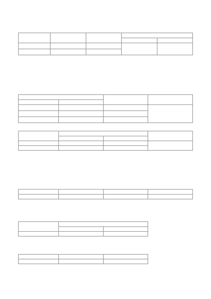
Output Characteristics
Amplitude
Distortion Minimum (CCW) Maximum (CCW)
Flatness
< 1MHz 1MHz - 10MHz
No Load ≥ 2Vp-p ≥ 20Vp-p
±1dB ±3dB
50 Ω ≥ Vp-p ≥ 10Vp-p
Notes:
1. Output impedance is 50Ω±10% @ 100kHz.
2. The amplitude should consider additional tolerance of atness.
3. FCCW: Full counterclockwise, FCW: Full clockwise.
4. Output protection: The generator main output is non-destructively protected against short circuit to ground or to any voltage
practically available in electronic laboratories. specication is specied within 10% to 100% of maximum output range, and the
waveform characteristics are limited to the specied range also.
Attenuator
Attenuator Switch
Attenuator @ 1kHz
-20dB -40dB
ON OFF -20dB
±2%OFF ON -40dB
ON ON -60dB
DC Offset
Load
DC Offset Knob - see Note 1
Ripple- see Note 2
FCCW FCW
No Load < -10V > +10V
≥ 10mVp-p
50 Ω < -5V > +5V
Notes:
1. Set the switch of DC OFFSET to ON position, and set the function switches of Sine, Triangle and Square to OFF position. Then test the
DC offset.
2. Before testing ripple, set the frequency range to lowest range and turn frequency knob to MIN position and be sure to set Amplitude
Knob at FCCW. Otherwise, it will induce noise around 50mVp-p based on different frequency.
Other Inputs and Outputs
Synchronous Output
Output Impedance Output level Transition time Fan out *2
50 Ω typical *1 TTL level, > 3V @ open circuit < 20 ns Typical 20 TTL loads
Notes:
1. The output Impedance is measured at 1kΩ load or above.
2. The capability of fan out depends on different TTL logics and the level is greater than 2V
Symmetry
Range
Symmetry Knob
FCCW FCW
Up to 1MHz ≤ 10% ≥ 90%
Notes:
1. Symmetry from 10% to 90% at full output amplitude terminated into 50Ω
External Sweep-IN
Impedance Sweep Range Sweep Ratio- see Note 1
14K Ω typical 0.2Hz~100Hz 1:100
Notes:
1. The frequency output will be proportional to the level of SWEEP-IN connector. 0–5V input for up to 100:1 frequency change
approximately. To avoid damage to this instrument, ensure that the maximum voltage into this BNC is no more than ± 10 Vp.
2. Turn off the Sweep ON switch.